


12
LA000578A © 2006 Navman New Zealand. All rights reserved. Proprietary information and specifications subject to change without notice.
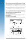
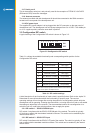
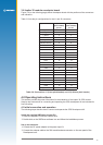
In addition to the congurable jumpers, there is a selection of test points on the board. The
signals available on the test points are shown in Table 3-5.
Test point Function
E1 TXA
E2 RXA
E3 TXB
E4 RXB
E6 1PPS
E7 not used
E8 ground
E9 ground
Table 3-5 Signals available on the test points
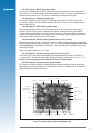
There are some settings that should not be changed when using the standard Jupiter 30 module
in conjunction with the development unit. These are as follows:
• SW2 must remain selected on 3.3 VDC
• Link for JB3/4 must be tted
• Link for JB16/17 must be tted
• SW3 DIP switch must be all off except SW3.3