


Engine Assembly
61
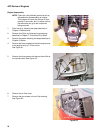
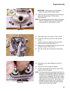
12. Rotate the piston so that the lettering on the connect-
ing rod bearing faces the crank shaft journal when
installed.
NOTE: Apply a coating of Slick 50
® or similar product to
the connecting rod bearing as a prelube.
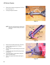
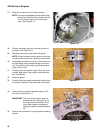
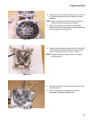
13. Slide the connecting rod onto the crankshaft pin.
Align the opening in the cylinder for cam bracket with
the cam bracket. See Figure 8.21.
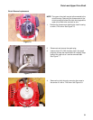
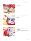
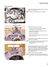
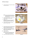
14. Apply a thread locking compound such as Loctite 266
to the cylinder head bolts. Install the cylinder head
bolts. Torque them to 65-70 in lbs (7 - 8 Nm).
NOTE: Tighten the cylinder head bolts in a “X” pattern.
See Figure 8.22.
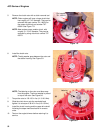
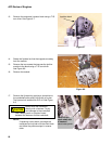
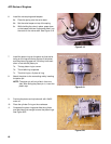
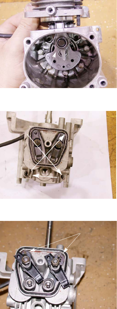
15. Pivot the rockers to the side and insert the push rods.
See Figure 8.23.
16. Set the valve lash by following the procedure
described in Chapter 2: Maintenance.
Figure 8.21
Slide the connecting
rod on first
Figure 8.22
1
23
4
Figure 8.23
Push rods