Ignition
23
Test the engine stop switch
To test the engine stop switch:
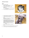
1. Open the grip by removing the five screws with a T-20
torx driver.
2. Disconnect the wires from the engine stop switch.
3. Connect an ohm meter or continuity light to the
switch.
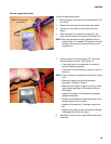
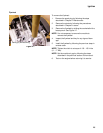
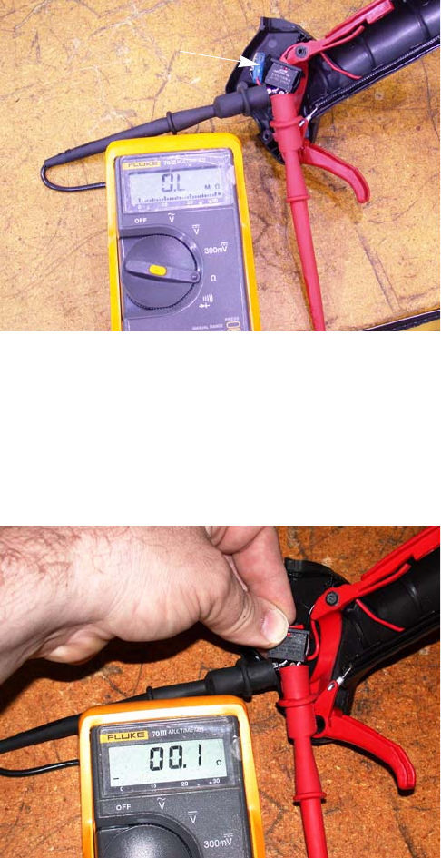
4. With the switch in the engine run position (l), the
meter should indicate no continuity. See Figure 4.3.
NOTE: Most stop switches are spring loaded to the run
position when it is released. This prevents no-start
situations caused by the customer failing to turn
the switch on.
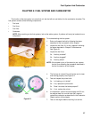
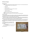
5. Hold the switch in the stop position (0). The meter
should indicate continuity. See Figure 4.4.
• If the results are not as described, the switch is
bad and should be replaced.
• If the switch is working properly, there is a short in
the wires.
NOTE: If there is reason to suspect that the ignition timing
is off:
• Remove the starter by following the steps
described in Chapter 6: Starter.
• Make sure the module air gap is correct by follow-
ing the steps described in the module section of
this chapter.
• Inspect the flywheel. If the flywheel is damaged,
replace the flywheel.
• Remove the flywheel by following the steps in the
flywheel section of this chapter.
• Inspect the flywheel key, if damaged replace the
key.
• Inspect the key way on the crank shaft for damage,
if damaged short block the engine.
6. Assemble and test run the engine before returning it
to service.
Figure 4.3
Switch in the engine
run position
Figure 4.4


