


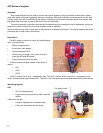
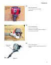
AC3 Series of engines
10
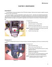
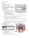
Valve lash
To adjust the valves:
NOTE: Loose valve lash on these engines can
mimic the symptoms of a lean fuel/air mix-
ture.
1. Remove the engine cover and spark plug, following
the steps described in the previous sections of this
chapter.
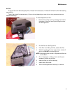
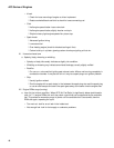
2. Remove the valve cover using a T-25 driver.
See Figure 2.13.
3. Rotate the crankshaft to bring the piston to top dead
center of the compression stroke (valves closed).
NOTE: Use a probe in the spark plug hole to track
the piston position.
NOTE: The valve clearance for this engine is
0.003”-.006”(.08-.15 mm) for both valves.
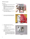
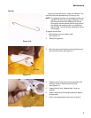
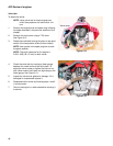
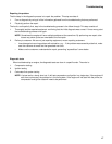
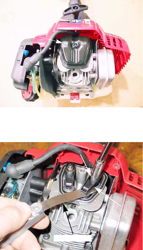
4. Check the valve lash by inserting a feeler gauge
between the rocker arm and the valve stem. To
adjust the valve, loosen or tighten the fulcrum nut
with a 8mm wrench until there is a slight drag on the
feeler gauge. See Figure 2.14.
5. Inspect the valve cover gasket for damage. If it is
damaged or compressed, replace it.
6. Reassemble the trimmer by following steps 1 and 2
in reverse order.
7. Test run the engine in a safe area before returning it
to service.
Figure 2.13
Valve cover
Figure 2.14
Fulcrum nut
Rocker
Feeler gauge