


ATD 50 Actuator
®
Operating Instructions
Page 7
3811 N. Holton Street • Milwaukee, WI • 53212 •USA • Phone • 414-906-4000 • Fax 414-906-4100 • www.MPCovers.com
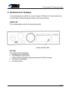
4 Design Information
4.1 Mechanical
All components in the system must be designed and installed to withstand the
forces produced by the system. This includes the door itself, all mounting brackets,
the idler pulley, the connector between the door and belt, and the door end stops.
Maximum tensile force of the belt 30 lbs (130 N)
Weight of the ATD 50 Actuator
®
unit 31 lbs (14Kg)
4.1.1 The Door
The door must have fixed positive stops at each end of travel. The stops must be
able to withstand the maximum pressure of the driving force (30 lbs /130 N).
Smooth door movement is the most important criteria to insure correct operation.
The door should have a consistent drag force over its complete travel. The door
guides should provide as low a drag resistance as possible. This will insure
trouble-free operation and will increase the drives’ sensitivity to any obstructions.
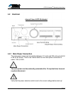
4.1.2 Installation Position
The ATD 50 Actuator
®
can be installed in any position and any orientation
according to the specific application. The drive belt, idler pulley, and ATD 50
Actuator
®
should be installed so that the moving parts do not touch or rub on any
other part of the machine. Also, the drive pulley and idler must be properly aligned
to insure correct belt travel. Failure to align the drive belt properly will result in
excessive belt wear and shortened belt life.
The ATD 50 Actuator
®
unit and the drive belt should be installed outside the area of
contamination. If the unit must be installed inside the area of contamination, the
drive belt must be protected from chips, coolants, or other debris.