


ATD 50 Actuator
®
Operating Instructions
Page 10
3811 N. Holton Street • Milwaukee, WI • 53212 •USA • Phone • 414-906-4000 • Fax 414-906-4100 • www.MPCovers.com
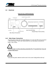
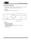
4.2.2 Control Connection
The ATD 50 Actuator
®
has a versatile microprocessor controller that interfaces with
the machine control unit. The parameters are factory-set. However, a
knowledgeable service technician can change the parameter settings using the
Microsoft Windows
®
‘95 based SERsoft programming software.
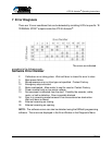
Inputs
An input is activated when an input terminal (IN) is connected to ground (GND).
This connection must be made using potential-free contacts. No external power
supply must be used to activate inputs.
Outputs
Six (6) potential free output relays are provided. Three (3) relays are wired as
normally open and three (3) are wired as normally closed. (See page 24)
5 Start-up Procedure
5.1 Preparation
Prepare the ATD 50 Actuator
®
by completing the following steps:
• Mount the drive box on a rigid base in a suitable position.
• Install the idler pulley to a rigid base on the machine.
• Cut the drive belt to length and splice together using the supplied clamp.
• Tension the drive belt by adjusting the idler pulley.
• Connect the drive belt to the door by fixing a bracket from the clamp to the door.
End-user must supply their own bracket.
• Verify that the door runs freely to both end-stops.
• Connect the input and output control cables and attach to the machine controller.
• Connect the main power cable. Do not apply power at this time!
The drive is now ready!