


ATD 50 Actuator
®
Operating Instructions
Page 11
3811 N. Holton Street • Milwaukee, WI • 53212 •USA • Phone • 414-906-4000 • Fax 414-906-4100 • www.MPCovers.com
5.2 Start-up
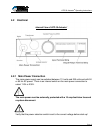
• Check the main power voltage selection switch for proper supply voltage (230V /
115V)
• Check the control connections and verify they are correctly installed
Beware of Electrical Voltages!
• Switch on the main power supply to the drive.
• Start the calibration run (see section below).
• Check and test all functions to be used.
• If required, re-adjust door-specific parameters (opening and closing speeds,
braking distance, etc.) using the SERsoft programming software.
• Test the complete system.
6 Check List for Functional Tests
During the functional tests the door travel path must be free of obstructions. The only
limits to door travel should be the two end-stops. Test the unit according to the
following steps:
TEST 1: POWER-UP
ACTION: Energize the main power to the ATD 50 Actuator
®
EXPECTED BEHAVIOR: No door movement.
Green LED on the Control Board illuminates.
Door is freely moveable.
No errors displayed on LED’ at terminals D5 - D9 (if
installed).
No errors displayed in the SERsoft Diagnostic Display.
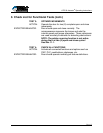
TEST 2: CALIBRATION RUN
ACTION: Apply momentary or maintained contact between OPEN
input (A2) and Ground (A1).
EXPECTED BEHAVIOR: Door moves slowly to open position and pushes against
end-stop.
Open position is now set in the microprocessor.
ACTION: Apply momentary or maintained contact of CLOSE input
(A7) and Ground (A1).
EXPECTED BEHAVIOR: Door moves slowly to closed position and pushes
against end-stop.
Closed position is now set in the microprocessor.