


ATD 50 Actuator
®
Operating Instructions
Page 15
3811 N. Holton Street • Milwaukee, WI • 53212 •USA • Phone • 414-906-4000 • Fax 414-906-4100 • www.MPCovers.com
9 Standard Input Functions
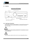
The ATD 50 Actuator
®
can accept either momentary or maintained contacts. The factory
default is momentary. If additional safety requirements are desired, you can specify
MAINTAINED CONTACT for the input signals. Maintained Contact Signals can be
programmed in the Basic Functions Menu in the SERsoft programming software.
If you desire to use maintained contacts for input signals, we suggest using the
following logic in your PLC or CNC:
The error signals for All Errors (General Error 1 - Relay 1 - E1 to E2) and
General Errors (General Error 2 - Relay 4 - E7 to E8) are activated during
calibration runs. The maintained contact can be held until the errors clear. In
this situation, the machine controller can monitor Relay 1 or 2 and maintain
the inputs to A2 and A7 until the errors clear.
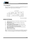
OPEN
This command will move the door to the full open position.
Input terminal: A2
Type of signal: Momentary or maintained contact A2 to Ground A1.
Active level Connection is normally open.
Close connection to activate.
Calibration run: After a software reset or a loss of main power, the first
portion of the calibration run is started with this command.
CLOSE
This command will move the door to the closed position.
Input terminal: A7
Type of signal: Momentary or maintained contact A7 to Ground A1.
Active level Connection is normally open.
Close connection to activate.
Calibration run: After a software reset or a loss of main power, the second
portion of the calibration run is started with this command.
The calibration run is completed when the door reaches the
closed position.