


Document Title: 7
User’s Manual for the GPS Orion-S/-HD Receiver
Document No. Issue 1.0
GTN-MAN-0110 June 22, 2003
DLR/GSOCNo part of this document shall be reproduced in any form or disclosed to third parties without prior authorization.
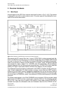
2.2 Interface Board
The interface board provides auxiliary devices that are required for standalone operation of
the Orion receivers. It comprises
• a switching regulator allowing operation from unregulated power supplies,
• a rechargeable battery to maintain the non-volatile memory and real-time clock during
power down times and
• two RS232 serial line drivers for communication with standard peripheral devices.
Key parameters of the interface board are summarized in Table 2.2.
Table 2.2 Physical and electrical parameters of GPS Orion interface board
Parameter Value
Dimension 95mm x 50mm x 20mm
Weight 70g
Operating voltage 8–30V
Efficiency of switching regulator 85%
Total power consumption (I/F and main board) 2.4 W
Battery +3.6V NiCad, 110 mAh ([1])
I/O ports 2 x RS232 (±10V)
Sub-D9 connector (male)
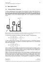
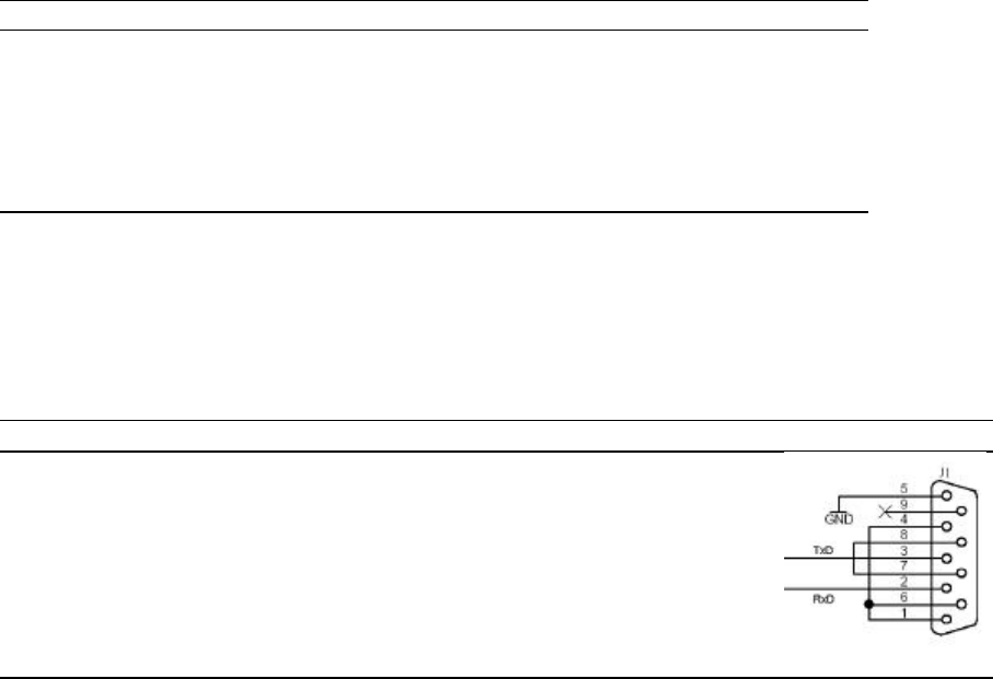
The two serial ports support the ground, receive and transmit line using the standard pin as-
signment for Sub-D9 connectors (Table 2.2). Pins 7 and 8 are cross-connected since the
Orion receiver does not support a hardware handshake. Likewise the three pins 1, 4, and 6
are connected among each other.
Table 2.2 Pin assignment for RS232 Sub-D9 connectors (Port A and B)
Pin Description Remarks Schematic
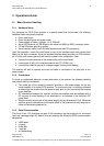
1 DCD (Data Channel Received
Line Signal Detector)
Connected with DTR and DSR (pins 4, 6)
2 RxD (Receive Data)
3 TxD (Transmit Data)
4 DTR (Data Terminal Ready) Connected with DCD and DSR (pins 1, 6)
5 GND (Signal Ground)
6 DSR (Data Set Ready) Connected with DCD and DTR (pins 1, 4)
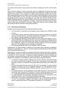
7 RTS (Request to Send ) Connected with CTS (pin 8)
8 CTS (Clear to Send) Connected with RTS (pin 7)
9 RI (Ring Indicator) Not connected
2.3 Antenna
The GPS Orion receiver is operated with an active antenna (or a passive antenna and exter-
nal preamplifier) having a minimum gain of 16 dB and a noise-figure of less than 4 dB More
specifically, the ANPC-131 antenna of M/A COM is recommended (cf. [4]), for terrestrial ap-
plications. It offers an LNA gain of +26 dB and a 1.5 dB noise-figure at the L1 frequency
(1575.42 MHz).
For space applications dedicated antenna designs with heat and vacuum resistant radomes
are generally required. For sounding rockets wrap around antennas, helix tip antennas or
blade antennas with separate preamplifiers are available on request. GPS antennas for
satellite applications are offered by e.g. Sensor Systems Inc.