


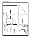
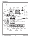
LRA Linear Residential Actuator Installation Guide - 5 - 228158 Revision X13 2-3-2009
Operator Setup
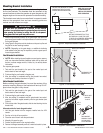
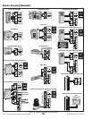
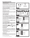
Operator Mounting
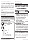
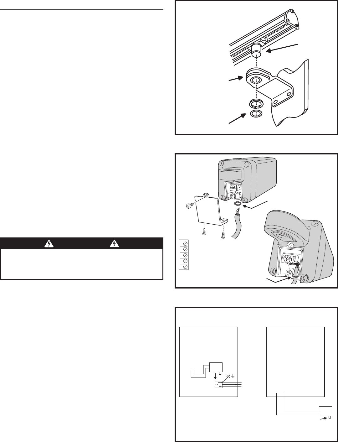
The operator mounts on the post bracket pin and into the
gate bracket bushing. Refer to Figure 5.
With the gate closed, carefully position the operator over the mounting 1.
brackets.
Lower the operator onto the post bracket pin while guiding the 2.
operator’s worm drive traveler shaft into the gate bracket bushing.
Install the washer and clip-ring on the post bracket pin.3.
Install the washer and clip-ring on the traveler shaft.4.
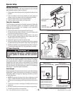
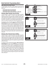
Controller Connection
The Controller is mounted in a locked enclosure. Open the
cover for installation access. The operator’s interface cable
plugs into the Controller and connects to the operator’s
5-position terminal block.
Remove the operator’s wiring access plate (see Figure 6).1.
Connect the interface cable to Terminals 1-5 on the Controller (see 2.
wire colors and terminal numbers in Figure 6).
Route the interface cable through a wiring knockout in the control 3.
box and towards the operator. Be sure to leave enough slack in the
interface cable to allow for the gate swing.
Slide the O-ring over the end of the interface cable.4.
Connect the interface cable to the operator’s terminal block matching 5.
the same colors and terminal numbers used in Step 2 (see Figure 6).
Replace the operator’s wiring access plate being careful to align the 6.
O-ring below the cable clamp. The O-ring helps keep out moisture.
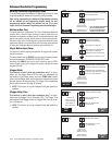
AC Power Connection
The control box contains a power disconnect switch to turn
on and off the power available to the operator. Following
wiring specifications on Page 2, incoming power should be
brought into the control box and connected to the labeled
pigtails from the disconnect box. A wiring connections print
can be found on the label inside the cover of the operator.
See Figure 7 for power option examples.
Earth Ground
Install a ground rod and connect it to the control box in every
installation. A good earth ground is necessary to allow the
Controller’s built-in surge and lightning protection circuitry
to work effectively.
✓ NOTE: Do not splice the ground wire. Use a single piece of solid
copper 12 AWG wire between the ground rod and the control box.
Install an 8-foot long copper ground rod within three feet of the control 1.
box.
Use a clamp to connect a solid copper 12 AWG ground wire to the 2.
ground rod.
Route the ground wire to the control box through a wiring knockout.3.
Connect the ground wire to the control box.4.
TRAVELER
SHAFT
GATE BRACKET
BUSHING
WASHER
AND CLIP-RING
Figure 5. Mounting the Operator
Figure 6. Interface Cable Connection
1 2 3 4 5
5 - OPEN LIMIT
4 - COMMON (LIMIT)
3 - CLOSE LIMIT
2 - MOTOR
1 - MOTOR
MATCH TERMINAL NUMBERS
ON OPERATOR & CONTROLLER
PUT O-RING ON CABLE TO
SEAL OUT MOISTURE
O-RING
FITS
IN SLOT
CONTROL BOX
TERMINAL STRIP
CONNECTION
24 VOLTS AC/DC
- +
GROUND
NEUTRAL
HOT
115V POWER
RECEPTACLE
BRING 115V HOT, NEUTRAL, AND
GROUND INTO CONTROL BOX AND
CONNECT TO POWER RECEPTACLE
PLUG TRANSFORMER INTO THE AC
RECEPTACLE, TRANSFORMER OUTPUT
CONNECTS TO THE TERMINAL STRIP
CONTROL BOX
TERMINAL STRIP
CONNECTION
24 VOLTS AC/DC
- +
PLUG-IN
TRANSFORMER
CONNECT TRANSFORMER
TO 115 VAC POWER SOURCE
POWER OPTION #1
(BRING 115V INTO CONTROL BOX)
POWER OPTION #2
(REMOTE LOCATED POWER SUPPLY)
IF BEYOND 500 FT. USE BRIDGE RECTIFIER
TO CONVERT 24 VAC TO 24 VDC AT
PLUG-IN TRANSFORMER LOCATION
MAXIMUM DISTANCE
500 FT. 12 GA. WIRE
Figure 7. Power and Ground Connections
WARNING
ALL AC ELECTRICAL CONNECTIONS TO THE POWER SOURCE AND
THE OPERATOR MUST BE MADE BY A LICENSED ELECTRICIAN
AND MUST OBSERVE ALL NATIONAL AND LOCAL ELECTRICAL
CODES.