


LRA Linear Residential Actuator Installation Guide - 20 - 228158 Revision X13 2-3-2009
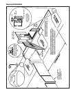
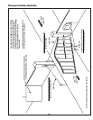
Dual Gate Installations
Two operators can be used in dual gate installations. The operators
communicate with each other through the 3-wire COMM LINK terminals.
When one operator activates, the COMM LINK connection signals
the other operator to activate. Each operator functions independently,
controlling its gate and monitoring its inputs and accessories.
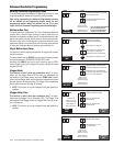
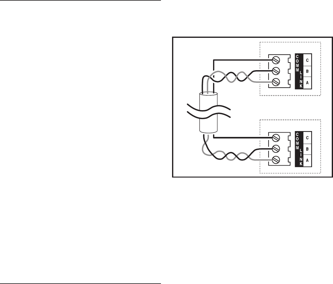
A three-wire shielded conductor cable is required to connect two operators
together for dual operation. Use Belden 8760 Twisted Pair Shielded Cable
(or equivalent) only – P/N 2500-1982, per foot).
✓ NOTE: The shield wire should be connected COMM LINK terminal
“C” in both operators.
Three of the programming functions available are only used for dual gate
installations:
Dual Gate Enable•
Dual Gate Enable must be set for all dual gate installations.
Stagger Mode•
The Stagger Mode function determines if the operator has a delayed
open or a delayed close. In dual swing gate installations, typically one
operator is programmed for delayed open, and the other operator is
programmed for delayed close.
Stagger Delay Time•
The Stagger Time sets the length of the delay for the Stagger Mode.
See Pages 11 & 13 for details on these three dual gate programming
functions.
Set the following parameters in each gate operator individually in a single gate
mode before connecting the network cable and operating in dual gate mode.
1. Open and Close Limit settings
2. Open and Closed direction inherent
entrapment protection (OC & CC)
After these parameters have been set, and each operator has been
tested independently and is functioning correctly in single gate mode,
then set BOTH operators to dual gate (dg) in the Paired Mode setup step
under Basic Programming steps.
Gate Operation
Open Button
Opens the gate. If the Controller is programmed to stop opening the
gate at mid-travel, a constant press of the OPEN button will override the
Mid-travel Stop and completely open the gate. If the Auto Close Timer is
set, it will be suspended until the OPEN button is released.
Close Button
Closes the gate if the gate is open. Also closes the gate if the gate is in
the process of opening.
Stop Button
Stops the gate from opening or closing at any time.
Single Input
Opens the gate if it’s closed and closes the gate if it’s open (open-close
programming option). Activating the input while the gate is moving will
reverse the gate.
Can be programmed to stop the gate while the gate is moving (open-
stop-close programming option).
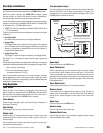
Fire Department Input
Fully opens the gate when the input is activated. Overrides the Mid-travel
Stop and Auto Close Timer (if either is programmed for the gate). The
gate will lockout in the open position without sounding the alarm. Press
the STOP button to release the lockout.
Open Input
Functions the same as the OPEN button.
Open Obstruction
While the gate opening, any open obstruction signal will cause the gate
to stop, reverse a short distance, and then stop again. The Auto Close
Timer will be disabled, and a renewed input will be required to start the
gate again. Should the gate be restarted and the obstacle signal occur
again prior to reaching a limit, the gate will stop again, lockout, and sound
the emergency alarm.
Close Obstruction
Same as the open obstruction, but in the closing direction.
Reverse Input
If the reverse input is triggered while the gate is closing, the gate will
reverse to the full open position. If the Auto Close Timer is set, when the
reverse input is cleared, the gate will close when the Auto Close Timer
expires.
Open Loop
Functions the same as the OPEN button.
Reverse Loop
Functions the same as the reverse input.
Shadow/Reset Loop
Holds the gate fully open or fully closed while triggered. If open, the gate
closes immediately when cleared.
OPERATOR #1
OPERATOR #2
USE BELDEN 8760 TWISTED PAIR
SHIELDED CABLE OR EQUIVALENT
SHIELD
CONNECT SHIELD
WIRE AT BOTH ENDS
DUAL GATE
COMM LINK
WIRING
CONNECT
C - C
B - B
A - A
SHIELD
Figure 14. COMM LINK Wiring