


LRA Linear Residential Actuator Installation Guide - 4 - 228158 Revision X13 2-3-2009
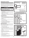
Mounting Bracket Installation
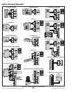
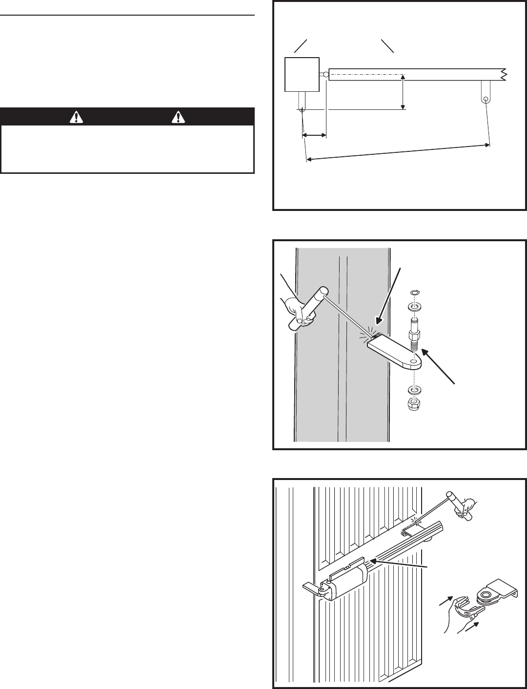
Examine Figure 2 for details of the required mounting locations
for the two brackets. The brackets must be mounted at the
correct locations to allow the operator to open the gate at a 90
degree angle and to ensure the operator functions smoothly.
The brackets must also be mounted level in respect to each
other so the operator’s front and rear mounting points are
vertical and not offset at an angle.
Measure approximately halfway up the gate height and determine 1.
good strong spots located in the required areas to mount the brackets
on the post and gate.
Using Figure 2 as a guide, mark the locations on the post or pillar and 2.
the gate for the two mounting brackets.
✓ NOTE: Depending on the gate design, an additional reinforcing
plate welded to the gate may be required to provide a good spot to
mount the gate bracket.
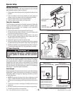
Post Bracket Installation
✓ NOTE: When installing the post bracket on a round post or masonry
pillar, use improvised methods (additional plate with lag bolts and
anchors, concrete wedge anchors, U-bolts, etc.) to securely fasten
the bracket.
For square gate posts:
Tack weld the post bracket to the post at the marked spot and 1.
double-check its level and height.
Finish welding the post bracket to the gate post.2.
After the welding is completed and the post bracket has cooled, 3.
install the post bracket pin as shown in Figure 3.
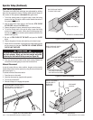
Gate Bracket Installation
Before welding the gate bracket, be sure the centers of the
operator mounting holes on the brackets will end up 29-1/2”
apart when the gate is fully closed.
Tack weld the gate bracket to the gate at the marked spot and 1.
double-check its level and height.
Finish welding the gate bracket to the gate.2.
After the welding is completed and the gate bracket has cooled, 3.
snap the limit switch magnet assembly onto the gate bracket (see
Figure 4).
From the top side of the gate bracket, slide the load bushing into the 4.
bracket hole.
Alternate method to locate the gate bracket:
1. Hold the gate bracket with the magnets installed onto the LRA
traveler.
2. Run the unit to the full open position.
3. Place the rear of the arm onto the post bracket.
4. Manually fully open the gate.
5. Position the gate bracket in the required position.
6. Remove the magnet assembly and bolt or weld the bracket in place.
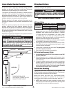
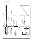
Figure 2. Required Bracket Locations
Figure 4. Gate Bracket Installation
WELD GATE
BRACKET
TO GATE
SNAP MAGNET
ASSEMBLY ONTO
GATE BRACKET
AFTER WELDING
USE A
LEVEL
29-1/2"
6"
5-1/2"
LOCATE POST BRACKET AT THESE
DIMENSIONS FROM THE GATE
CENTERLINE AND HINGE POINT
SETTING THE BRACKETS AT THIS
DISTANCE WILL CAUSE THE GATE
TO OPEN AT 90 DEGREES (DEPENDING
ON THE LIMIT SWITCH SETTINGS)
NOTE: THE 5-1/2" AND
6" DIMENSIONS ARE
CRITICAL FOR PROPER
GATE OPERATION
WELD POST BRACKET
TO POST
ASSEMBLE POST
BRACKET PIN
Figure 3. Post Bracket Installation
WARNING
The gate must be installed in a location so that enough
clearance is supplied between the gate and adjacent structures
when opening and closing to reduce the risk of entrapment.
Swing gates shall not open into public areas.