


LRA Linear Residential Actuator Installation Guide - 2 - 228158 Revision X13 2-3-2009
Linear Actuator Operator Overview
The Model LRA Residential Linear Actuator is designed
to open and close a light-duty residential swing gate. The
operator can be used in left-hand or right-hand swing gate
installations on gates weighing up to 600 pounds.
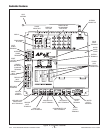
The operator is connected by a cable to an APeX electronic
controller, which provides all connections for input and
entrapment detection devices. The Controller is housed in a
separate enclosure and contains a built-in radio receiver for
wireless activation by remote control transmitters.
Brackets attached to the gate and gate hinge post are for
mounting the operator and to provide a mechanism to move
the gate.
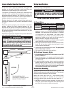
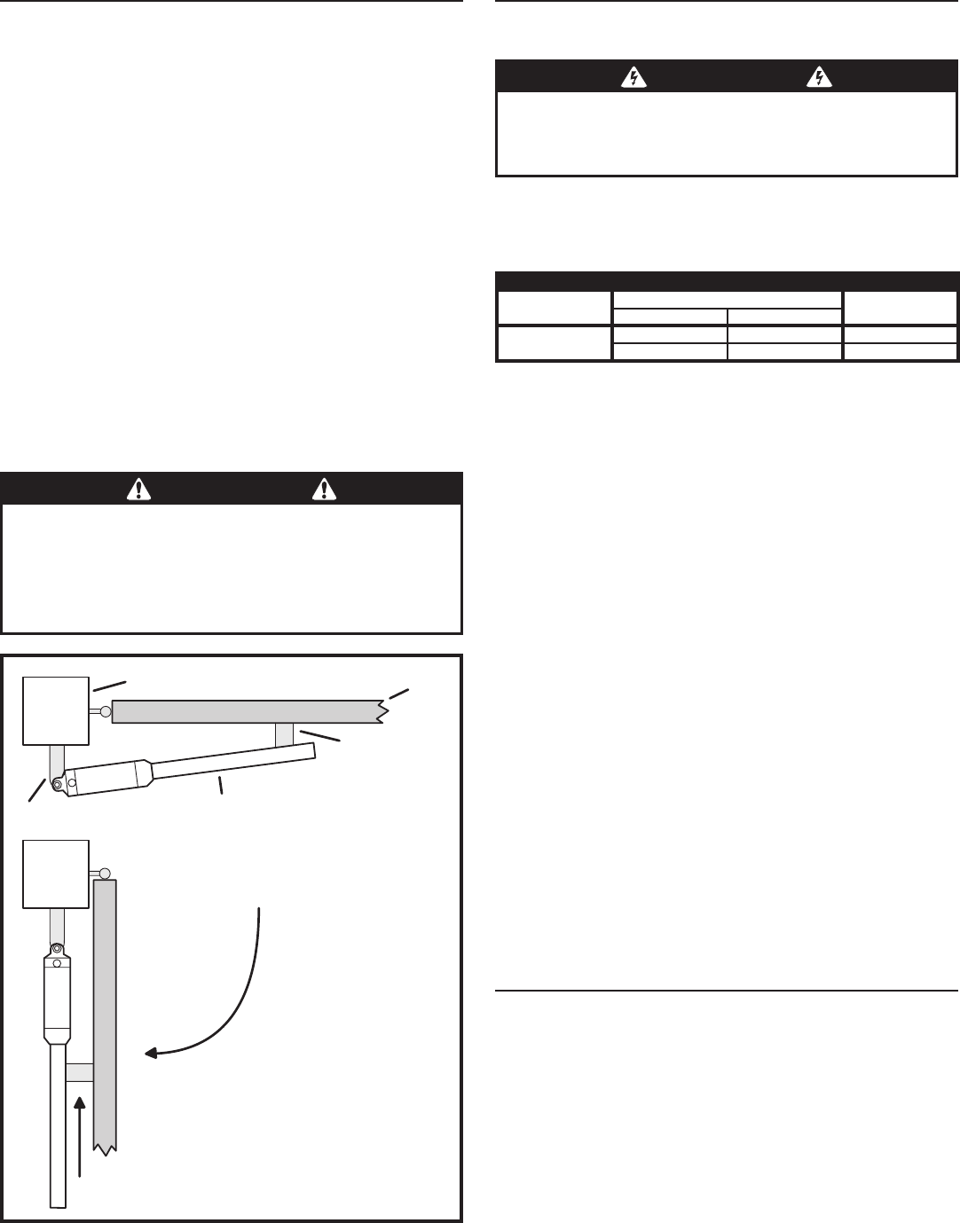
When the operator activates, the worm drive in the linear
actuator changes the fixed distance between the two
brackets that the operator is mounted on. When the operator
pulls the two brackets closer together, the gate opens. When
the operator pushes the two brackets farther apart, the gate
closes (see Figure 1).
Adjustable magnetic limit switches in the operator detect the
open and closed positions of the gate.
Wiring Specifications
Refer to the following steps for details on power and
accessory wiring for the operator.
AC Power Wiring
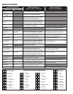
MODEL LRA POWER WIRING
SUPPLY VOLTS
MAXIMUM DISTANCE (FEET)
WIRE GAUGE
SINGLE DUAL
115 VOLTS
3288 1644 14
5224 2612 12
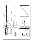
The distance shown in the table above is measured in feet from the 1.
operator to the power source. DO NOT EXCEED THE MAXIMUM
DISTANCE. These calculations have been based on a standard
115 V supply with a 10% drop allowable. If your supply is under
the standard rating, the runs listed may be longer than what your
application will handle, and you should not run wire too near the
maximum distance for the gauge of wire you are using.
When large-gauge wire is used, a separate junction box (not supplied) 2.
may be needed for the operator power connection.
Wire length calculations are based on the National Electrical Code, 3.
Article 430 and have been carefully determined based on motor
inrush and operator requirements.
Connect power in accordance with local codes. 4. The green ground
wire must be properly connected.
Wire insulation must be suitable to the application.5.
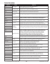
DC Control and Accessory Wiring
All control devices are now 24 VDC, which can be run up to 2000 1.
feet with 14 AWG wire.
Control wiring must be run in a separate conduit from power wiring. 2.
Running them together may cause interference and faulty signals in
some accessories.
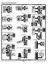
A three-wire shielded conductor cable is required to connect two 3.
operators together for dual operation. You must use Belden 8760
Twisted Pair Shielded Cable (or equivalent) only – P/N 2500-1982,
per foot). See Page 20 for details of this connection. Note: The shield
wire should be connected in both the Controllers.
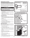
Control Box Mounting
Locate the control box in the vicinity of the operator. The
APeX Controller mounts inside the control box. The operator
connects to the Controller via a 6-foot cable.
Mount the control box firmly to a non-movable object.
Knockouts are provided for conduits. Do not mount the
control box where a lawn sprinkler may spray water on it.
✓ NOTE: When installing the cable connecting the operator to the
control box, be sure to leave some slack to allow for the swing of the
gate. Water tight connectors are highly recommended.
WARNING
ALL AC ELECTRICAL CONNECTIONS TO THE POWER SOURCE AND
THE OPERATOR MUST BE MADE BY A LICENSED ELECTRICIAN
AND MUST OBSERVE ALL NATIONAL AND LOCAL ELECTRICAL
CODES
USE COPPER WIRE ONLY!
WARNING
This operator is intended for installation only on gates used for
vehicles. Pedestrians must be supplied with a separate access
opening. The pedestrian access opening shall be designed to
promote pedestrian usage. Locate the gate such that persons
will not come into contact with the vehicular gate during the
entire path of travel of the vehicular gate.
GATE POST
GATE
ACTUATOR
GATE CLOSED
GATE OPEN
THE ACTUATOR PULLS THE
GATE BRACKET TOWARDS THE POST
BRACKET TO OPEN THE GATE
GATE BRACKET
POST BRACKET
Figure 1. Linear Actuator Operation