


LRA Linear Residential Actuator Installation Guide - 2 - 228158 Revision X13 2-3-2009
Table of Contents
Pre-installation Information . . . . . . . . . . . . . . . . . . . . . . . . . . . . . . . . . .1
Before You Begin... . . . . . . . . . . . . . . . . . . . . . . . . . . . . . . . . . . . . . .1
Always Check the Gate’s Action . . . . . . . . . . . . . . . . . . . . . . . . . . . .1
Gate Operator Classifications . . . . . . . . . . . . . . . . . . . . . . . . . . . . . .1
Approved Obstruction Detection Devices . . . . . . . . . . . . . . . . . . . . .1
Safety Information and Warnings ..............................1
Regulatory Warnings .....................................1
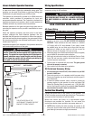
Linear Actuator Operator Overview ............................2
Wiring Specifications . . . . . . . . . . . . . . . . . . . . . . . . . . . . . . . . . . . . . . .2
AC Power Wiring . . . . . . . . . . . . . . . . . . . . . . . . . . . . . . . . . . . . . . . .2
DC Control and Accessory Wiring ...........................2
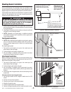
Control Box Mounting .......................................2
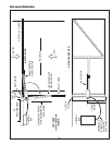
Gate Layout Illustration. . . . . . . . . . . . . . . . . . . . . . . . . . . . . . . . . . . . . .3
Mounting Bracket Installation . . . . . . . . . . . . . . . . . . . . . . . . . . . . . . . .4
Post Bracket Installation . . . . . . . . . . . . . . . . . . . . . . . . . . . . . . . . . .4
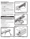
Gate Bracket Installation ..................................4
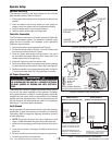
Operator Setup . . . . . . . . . . . . . . . . . . . . . . . . . . . . . . . . . . . . . . . . . . . .5
Operator Mounting . . . . . . . . . . . . . . . . . . . . . . . . . . . . . . . . . . . . . .5
Controller Connection . . . . . . . . . . . . . . . . . . . . . . . . . . . . . . . . . . . .5
AC Power Connection ....................................5
Earth Ground ...........................................5
Limit Switch Adjustment . . . . . . . . . . . . . . . . . . . . . . . . . . . . . . . . . .6
Manual Disconnect . . . . . . . . . . . . . . . . . . . . . . . . . . . . . . . . . . . . . .6
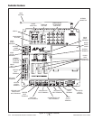
Controller Features .........................................7
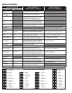
Indicator Descriptions .......................................8
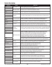
Terminal Descriptions .......................................9
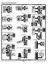
Operator Accessory Connections ............................10
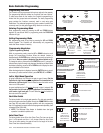
Basic Controller Programming. . . . . . . . . . . . . . . . . . . . . . . . . . . . . . .11
Programming Overview ..................................11
Entering Programming Mode . . . . . . . . . . . . . . . . . . . . . . . . . . . . .11
Exiting Programming Mode ...............................11
Programming Keystrokes . . . . . . . . . . . . . . . . . . . . . . . . . . . . . . . .11
Left or Right Hand Operation. . . . . . . . . . . . . . . . . . . . . . . . . . . . . .11
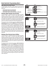
Dual Gate Enable . . . . . . . . . . . . . . . . . . . . . . . . . . . . . . . . . . . . . .11
Auto Close Timer .......................................11
Run Alarm and Pre-start Alarm ............................12
Maximum Open Direction Current Setting ....................12
Maximum Close Direction Current Setting . . . . . . . . . . . . . . . . . . .12
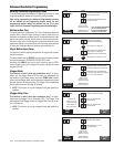
Advanced Controller Programming ...........................13
Entering Advanced Programming Mode . . . . . . . . . . . . . . . . . . . . .13
Maximum Run Time . . . . . . . . . . . . . . . . . . . . . . . . . . . . . . . . . . . .13
Single Button Input Setup . . . . . . . . . . . . . . . . . . . . . . . . . . . . . . . .13
Stagger Mode . . . . . . . . . . . . . . . . . . . . . . . . . . . . . . . . . . . . . . . . .13
Stagger Delay Time .....................................13
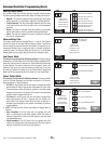
Auxiliary Relay Mode ....................................14
Reverse Delay Time . . . . . . . . . . . . . . . . . . . . . . . . . . . . . . . . . . . .14
Low Power Mode .......................................14
Power Failure Mode .....................................14
Soft Start/Stop Duration . . . . . . . . . . . . . . . . . . . . . . . . . . . . . . . . .15
Reset Cycle Count . . . . . . . . . . . . . . . . . . . . . . . . . . . . . . . . . . . . .15
Maintenance Alert Trigger ................................15
Mid-travel Stop Position ..................................15
Motor Type Selection ....................................15
Radio Enable ..........................................16
Antenna Installation .....................................16
Radio Transmitter Learn . . . . . . . . . . . . . . . . . . . . . . . . . . . . . . . . .16
Radio Transmitter Delete .................................16
MGT Obstacle Transmitter Learn . . . . . . . . . . . . . . . . . . . . . . . . . .16
MGT Obstacle Transmitter Delete ..........................16
Reset Controller to Factory Defaults ........................16
Loop Layout Illustration . . . . . . . . . . . . . . . . . . . . . . . . . . . . . . . . . . . .17
Safety Edge Layout Illustration . . . . . . . . . . . . . . . . . . . . . . . . . . . . . .18
Photoeye Installation Illustration .............................19
Dual Gate Installations . . . . . . . . . . . . . . . . . . . . . . . . . . . . . . . . . . . . .20
Gate Operation ............................................20
Open Button . . . . . . . . . . . . . . . . . . . . . . . . . . . . . . . . . . . . . . . . . .20
Close Button . . . . . . . . . . . . . . . . . . . . . . . . . . . . . . . . . . . . . . . . . .20
Stop Button . . . . . . . . . . . . . . . . . . . . . . . . . . . . . . . . . . . . . . . . . . .20
Single Input ...........................................20
Fire Department Input ...................................20
Open Input ............................................20
Open Obstruction . . . . . . . . . . . . . . . . . . . . . . . . . . . . . . . . . . . . . .20
Close Obstruction . . . . . . . . . . . . . . . . . . . . . . . . . . . . . . . . . . . . . .20
Reverse Input . . . . . . . . . . . . . . . . . . . . . . . . . . . . . . . . . . . . . . . . .20
Open Loop ............................................20
Reverse Loop . . . . . . . . . . . . . . . . . . . . . . . . . . . . . . . . . . . . . . . . .20
Shadow/Reset Loop . . . . . . . . . . . . . . . . . . . . . . . . . . . . . . . . . . . .20
Operation Indications . . . . . . . . . . . . . . . . . . . . . . . . . . . . . . . . . . . . . .21
Power-up Display .......................................21
Idle Condition . . . . . . . . . . . . . . . . . . . . . . . . . . . . . . . . . . . . . . . . .21
Last Gate Position/Condition ..............................21
Pre-start Delay . . . . . . . . . . . . . . . . . . . . . . . . . . . . . . . . . . . . . . . .21
Reverse Delay .........................................21
Run Timer . . . . . . . . . . . . . . . . . . . . . . . . . . . . . . . . . . . . . . . . . . . .21
Error Indications . . . . . . . . . . . . . . . . . . . . . . . . . . . . . . . . . . . . . . . . . .21
Entrapment . . . . . . . . . . . . . . . . . . . . . . . . . . . . . . . . . . . . . . . . . . .21
COMM LINK Connection Failure ...........................21
MGT Obstacle Transmitter Trouble . . . . . . . . . . . . . . . . . . . . . . . . .21
Maximum Run Time Exceeded ............................21
Troubleshooting ...........................................22
Contacting Technical Support . . . . . . . . . . . . . . . . . . . . . . . . . . . . .22
Operator fails to start ....................................22
Motor operates, but gate does not move .....................22
Motor sounds like it is working harder than normal .............22
Gate stopping part way open or closed (but no visible obstruction) 22
Gate staying open with automatic system ....................22
How to Order Replacement Parts . . . . . . . . . . . . . . . . . . . . . . . . . .22
Model LRA Replacement Parts . . . . . . . . . . . . . . . . . . . . . . . . . . . . . .23
Preventative Maintenance . . . . . . . . . . . . . . . . . . . . . . . . . . . . . . . . . .24
General . . . . . . . . . . . . . . . . . . . . . . . . . . . . . . . . . . . . . . . . . . . . . .24
Lubrication ............................................24
6-Month Preventative Maintenance .........................24
Battery Maintenance ....................................24
FCC Notice ...............................................24
Gate Operator Installation Checklist ..........................26
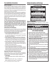
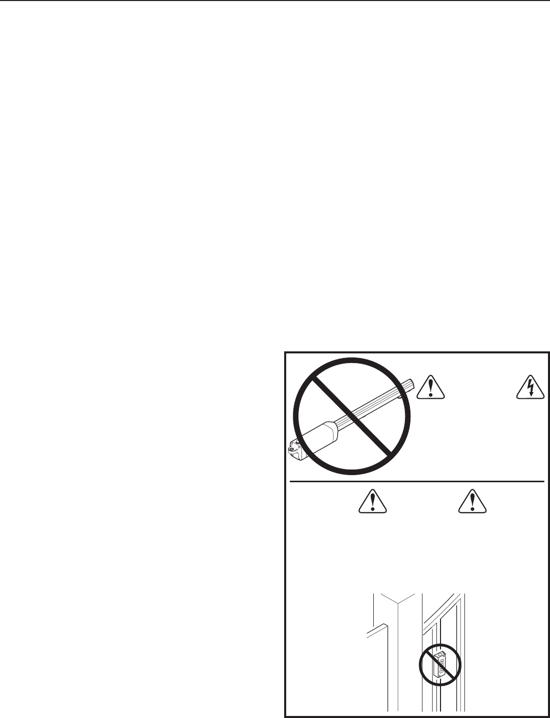
ONLY QUALIFIED TECHNICIANS
SHOULD WORK ON
LINEAR RESIDENTIAL
ACTUATORS
WARNING
WARNING
CONTROLS INTENDED FOR USER ACTIVATION MUST BE
LOCATED AT LEAST SIX FEET (6') AWAY FROM ANY MOVING
PART OF THE GATE AND WHERE THE USER IS PREVENTED
FROM REACHING OVER, UNDER, AROUND OR THROUGH THE
GATE TO OPERATE THE CONTROLS. OUTDOOR OR EASILY
ACCESSIBLE CONTROLS SHALL HAVE A SECURITY FEATURE
TO PREVENT UNAUTHORIZED USE.