


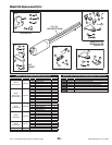

LRA Linear Residential Actuator Installation Guide - 21 - 228158 Revision X13 2-3-2009
Operation Indications
During normal operation, the Controller’s displays will
indicate current operating conditions and status.
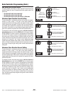
Power-up Display
When the Controller powers up, dashes will show on the
display for one second, then the firmware version number
will be displayed for one second.
Exiting programming restarts the Controller. The power-up
display will show upon the restart.
Idle Condition
While the Controller is idling, waiting for a command, the
display will show circulating dashes.
For DC models only - Clockwise : Batteries discharging,
Counterclockwise : Batteries charging
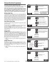
Last Gate Position/Condition
When the gate moves or stops, the display will show the
status for up to one minute.
Stop is displayed as • St
Full Close is displayed as • FC
Full Open is displayed as • FO
Entrapment is displayed as • En
Pre-start Delay
During the pre-start delay, the display will countdown the
number of seconds remaining before the operator starts.
Reverse Delay
If the gate travel direction is reversed from a user activation or
reversing device, and a reverse delay is set, the display will count
down the delay time in seconds before the operator restarts.
Run Timer
While the gate is opening or closing, the number of seconds
running time is displayed.
Error Indications
During abnormal operation, the Controller’s displays and
beeper will indicate the error condition that has occurred.
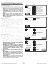
Entrapment
If an entrapment condition occurs detected by two repeated
open or close obstruction triggers, the Controller will lock
the operator out. The beeper will sound constantly and the
gate will not operate. To reset the Controller press the STOP
button or press the RESET button on the control box.
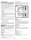
COMM LINK Connection Failure
In dual gate installations, if there is a connection failure between
the two operators, the COMM LINK indicator will blink once a
second. During this condition the gate will not operate, except
if triggered by the FIRE DEPT input, which functions normally.
MGT Obstacle Transmitter Trouble
If any MGT transmitters are used with the operator, their
supervision feature will alert the Controller if there is any
trouble with the transmitter. MGT transmitters send hourly
status reports and will send low battery reports when the
transmitter has a low battery. The MGT transmitters also
have a tamper detection switch that will trigger when their
case is opened.
When the Controller detects a low transmitter battery, a
tamper signal, or missing transmitter status reports, the
gate will still operate normally, but the beeper will change
as follows:
The Pre-start Alarm will beep twice as fast.•
The Run Alarm will beep twice as fast and continue for five minutes •
after the gate stops.
The sounder will “chirp” every five seconds when the gate is idle.•
Correct the trouble (close case, replace battery, or replace
transmitter) to clear the obstacle transmitter trouble
indications.
Maximum Run Time Exceeded
If the Maximum Run Time is exceeded, the Controller stops
the operator the same as if a double obstacle has occurred
in an entrapment condition. The entrapment alarm sounds
constantly, and is cleared by pressing the STOP button or the
RESET button on the cover. After the STOP or RESET button
is pressed, because the Maximum Run Time has been
exceeded, the sounder will beep twice every five seconds.
The next operation of the gate will clear the indication.
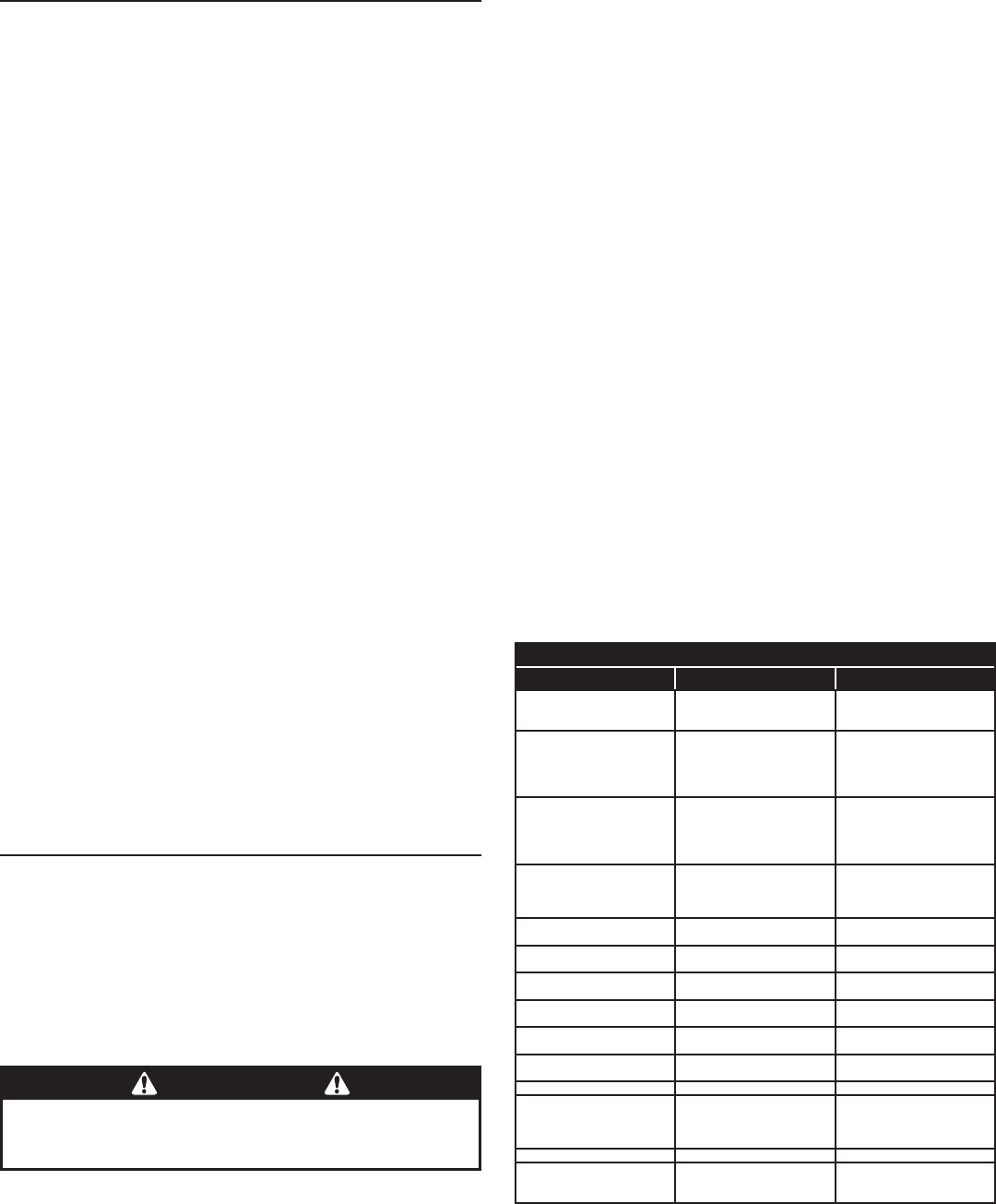
CONTROLLER ERROR CAUSES AND INDICATIONS
ERROR CAUSE ERROR INDICATION HOW TO CLEAR
TWO SAFETY REVERSALS (ON
SINGLE GATE OR ON EITHER
DUAL GATE)
En 00, CONTINUOUS ALARM
BEEPER, GATE DISABLED
PRESS STOP BUTTON
MAXIMUM RUN TIMER
EXCEEDED ON OPENING
En 01, AND MAX RUN LED,
CONTINUOUS ALARM BEEPER,
GATE DISABLED
PRESS STOP BUTTON,
CLEARS CONTINUOUS ALARM,
THEN DOUBLE BEEP EVERY
5 SECONDS UNTIL NEXT
OPERATION
MAXIMUM RUN TIMER
EXCEEDED ON CLOSING
En 02, AND MAX RUN LED,
CONTINUOUS ALARM BEEPER,
GATE DISABLED
PRESS STOP BUTTON,
CLEARS CONTINUOUS ALARM,
THEN DOUBLE BEEP EVERY
5 SECONDS UNTIL NEXT
OPERATION
COMM LINK FAILURE
En 03, AND COMM LINK LED,
CONTINUOUS ALARM BEEPER
FOR 1 MINUTE, GATE DISABLED
(EXCEPT FOR FIRE DEPT INPUT)
PRESS STOP BUTTON, CLEARS
CONTINUOUS ALARM
GATE FULL OPEN RESULTING
FROM FIRE DEPT INPUT
En 04, GATE DISABLED PRESS STOP BUTTON
FAIL SAFE OR FAIL SECURE
BECAUSE OF AC POWER LOSS
En 05, GATE DISABLED
BATTERY VOLTAGE MUST RISE
ABOVE 24 VDC
OTHER CONTROLLER IN
ENTRAPMENT (DUAL GATE)
En 06, GATE DISABLED
CLEAR ENTRAPMENT ON OTHER
CONTROLLER (PRESS STOP)
LOW AC VOLTAGE AT
CONTROLLER
En 07, GATE DISABLED
LOW VOLTAGE AC POWER MUST
RISE ABOVE 20 VAC
INPUT TRIGGERED DURING
ENTRAPMENT LOCKOUT
En 08, GATE DISABLED PRESS STOP BUTTON
COMPATIBILITY PROBLEM En 09, GATE DISABLED
UPDATE FIRMWARE AND RESET
BOTH PAIRED CONTROLLERS
EEPROM PROBLEM En 10, GATE DISABLED TRY RESET, CALL TECH. SUPPORT
DC MOTOR MISMATCH En 11, GATE DISABLED
REPROGRAM MOTOR TYPE OR
CHANGE DC MOTOR BOARD,
NEXT GATE MOVEMENT WILL
RETRY DC MOTOR CHECK
MOTOR FAILURE En 12, GATE DISABLED REPLACE MOTOR
MGT SUPERVISORY CONDITION
(TAMPER, LOW BATTERY,
MISSING HOURLY STATUS)
FAST BEEPS DURING PRESTART,
FAST BEEP RUN ALARM, CHIRP
EVERY 5 SECONDS AT IDLE
CLEARS WHEN MGT CONDITION
CLEARS
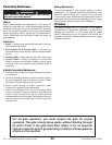
WARNING
The Stop and/or Reset button must be located in the line-of-
sight of the gate. Activation of the reset control shall not
cause the operator to start.