6 ASSEMB
LY
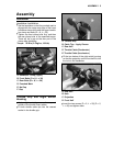
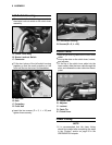
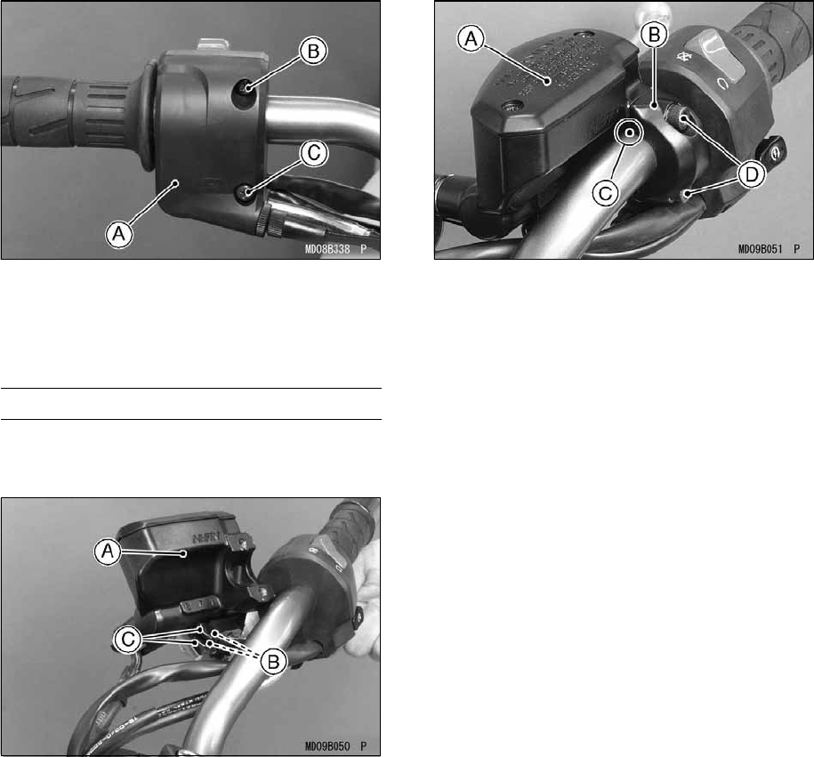
A. Right Switch Housing
B. Screw (D = 5, L = 25)
C. Screw (D = 5, L = 40)
Front Brake Master Cylinder
•
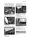
Connect the right switch housing lead con-
nectors to the front brake light switch termi-
nals on the front brake master cylinder.
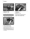
A. Front Master Cylinder
B. Brake Light Switch Terminals
C. Connectors and Dust Covers
•
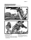
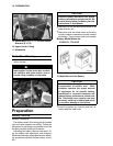
Install the front master cylinder with its clamp
and the two bolts (D = 6, L = 22).
•
Position the master cylinder so that the mat-
ing surface of the front and rear master cylin-
der clamps align with the punched mark on
the handlebar.
A. Front Master Cylinder
B. Clamp
C. Punched Mark
D. Bolts (D = 6, L = 22)
•
Tighten the upper clamp bolt first and then the
lower clamp bolt to the specified torque.
Torque: 11 N·m (1.1 kgf·m, 97 in·lb)


