


PREPARA
TION 21
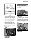
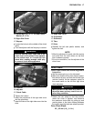
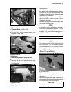
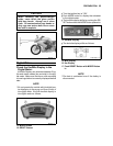
A. Dust Cover
B. Meter Unit Connector
C. Flanged Bolts (D = 6, L= 12)
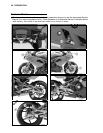
•
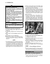
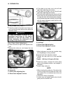
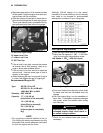
Pull the upper fairing outward to clear the
stoppers on both sides.
•
Remove the upper fairing forward.
A. Upper Fairing
B. Stoppers
C. Remove the Upper Fairing Forward.
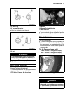
•
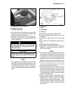
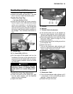
Remove the cap from the reserve tank and
add coolant through the filler opening to the F
(Full) level line.
A. Reserve Tank
B. Cap
C. F (Full) Level Line
•
Install the cap.
•
Reinstall the upper fairing and meter cover in
the reverse order of the removal procedure.
•
Connect the city light lead connectors, head
light lead connectors and turn signal light lead
connectors on both sides.
•
Reinstall the right side cover (see the “Clutch
Lever and Cable” section on page 16 in the
Preparation chapter).
•
Reinstall the left side cover in the same man-
ner as the right side cover.
NOTE
żA per
manent type of antifreeze is installed in
the cooling system when shipped. It is col-
ored green and contains ethylene glycol. It is
mix
ed at 50% and has the freezing point of
–35 °C (–31 °F).
Eng
ine Oil (4-stroke)
Engine Oil Level Inspection
NOTE
żThi
s vehicle’s engine is filled with 20W-40 oil
from the factory. DO NOT DRAIN and refill
the crankcase before use. Check oil level and
dra
in plug tightness.
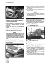
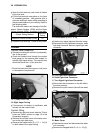
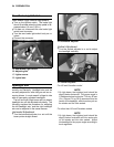
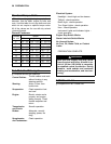
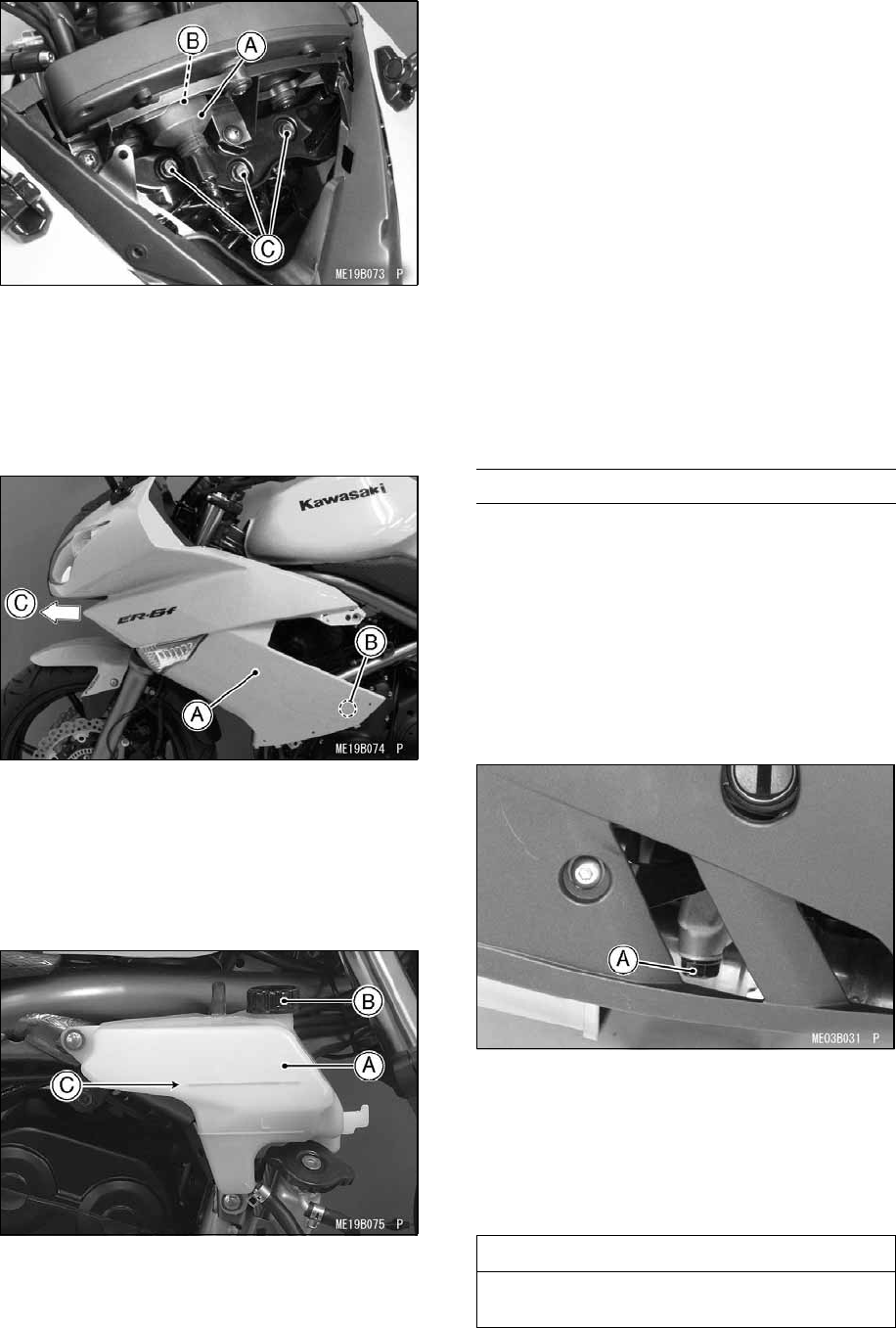
Engine Oil Drain Plug Torque:
30 N·m (3.1 kgf·m, 22 ft·lb)
A. Oil Drain Plug
•
Park the vehicle on level ground.
•
Before starting the engine, check that the en-
gine has oil.
•
With the motorcycle held level, check that the
engine has oil through the oil level sight gauge
in the lower right side of the engine.
CAUTION
If the engine is run without oil, it will be
severely damaged.