


N
KRA 405B RADAR ALTIMETER INSTALLATION MANUAL
Page 2-16
006-10536-0010 Rev. 10 Oct/2005
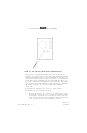
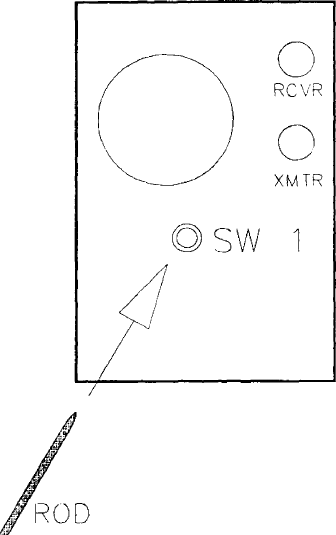
FIGURE 2-4 KRA 405B POST INSTALLATION CALIBRATION SWITCH
Verify proper on ground performance after the calibration is
complete. For systems without a zero feet offset programmed into the
configuration module, this will be an indication of zero feet plus
or minus the system tolerance of two or three feet. For systems with
a zero feet offset programmed into the configuration module, this
will be an indication of the negative value of the zero feet offset
plus or minus the system tolerance of two or three feet. Note that
the analog indicators may not allow quantifiable negative
indications.
A KRA 405B with software 01/04, 02/04, or higher contain
enhancements to the calibration routine.
1. When the calibration is in process, the KRA 405B will output
an altitude of 500 feet. This relieves the 10-second switch
requirement. The switch may be released as soon as the indi-
cator displays 500 feet. If the indicator does not display 500
feet, the switch has not been adequately pressed.