


N
KRA 405B RADAR ALTIMETER INSTALLATION MANUAL
Page 2-12
006-10536-0010 Rev. 10 Oct/2005
• Antennas must not be located in areas where excess water can ac-
cumulate. Water between the antenna flange and aircraft skin
will cause loss of system sensitivity and may cause peeking.
• The connectors on the KA 54 antennas should be mounted perpen-
dicular to a line drawn through the receive and transmit antennas
for a given unit. The antennas are designed for minimum coupling
when mounted as above. Any other mounting may cause the altim-
eter to lock on to erroneous altitudes when flying above 2500
feet AGL.
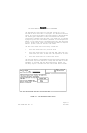
• The KA 54A antennas are oriented by observing the arrows pointed
on the outer side of the antenna. The arrows on the transmit and
receive antennas for a given unit must be on the same longitudi-
nal axis. This is achieved by having the arrow head of one an-
tenna pointing to the tail of the other antenna arrow (see FIGURE
2-7 DUAL RADAR ALTIMETER SYSTEM TYPICAL ANTENNA INSTALLATIONS).
Alternately, the two arrows may point at each other as long as
they remain on the same longitudinal axis.
If a side by side dual installation is chosen, the transmit an-
tennas from the two units should be next to each other and the
receive antennas should be next to each other (see FIGURE 2-7
DUAL RADAR ALTIMETER SYSTEM TYPICAL ANTENNA INSTALLATIONS).
E. IMPLEMENTING THE ANTENNA INSTALLATION
NOTE: Antenna and airframe surfaces must be free of paint or
other insulating materials, including chromate. Apply
Alumiprep #33 (P/N 016-01127-0000) to cleanse the metal
of any residue left after removing paint or insulating
material. Protect bare aluminum surfaces with Alodine
1001 (P/N 016-01128-0000) or equivalent prior to mounting
antennas or bonding straps. Bonding resistance should be
2.6 milliohms or less for the best operation of the an-
tenna system.
• RF/Air sealing gaskets are to be installed between KA 54A mount-
ing flanges and aircraft skin.
• Minimum and maximum allowable lengths for each set of RF cables
(receive and transmit) must be appropriate for proper installa-
tion. System sensitivity suffers when cables lengths do not com-
ply with the recommended minimum and maximum lengths. (Refer to
TABLE 1-2 CABLE INSTALLATIONS).
• Make sure the cables are tight inside the cable connectors.