


N
KRA 405B RADAR ALTIMETER INSTALLATION MANUAL
Page 1-1
006-10536-0010 Rev. 10 Oct/2005
SECTION I
GENERAL INFORMATION
1.0 INTRODUCTION
This manual contains information relative to the physical, mechanical, and
electrical characteristics of the BENDIX/KING KRA 405B. Installation and
operating procedures are also included. Information relative to the
maintenance and procurement of replacement parts may be found in the KRA
405B Maintenance Manual Part Number 006-15536-00XX (XX = Highest
Revision).
NOTE: The KRA 405B System consists of four modules: the Radar Altim-
eter (Receiver/Transmitter), the Radar Altimeter Indicator, the
Radar Altimeter Antennas (2 each), and the CM 2000 Configuration
Module (optional). The system is positioned as a replacement
for the KRA 405 Radar Altimeter System.
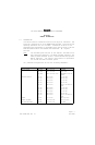
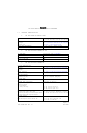
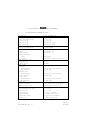
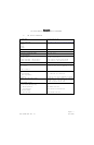
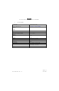
The preferred configurations utilize the following components:
COMPONENT UNIT PART NUMBER CHARACTERISTIC
RADAR ALTIMETER KRA 405B 066-01153-0101 STANDARD
KRA 405B 066-01153-0202 ARINC 552A
KRA 405B 066-01153-2001/-4001 ENHANCED DIGITAL AC-
CURACY
CONTROLLER/DISPLAY KNI 415 066-3031-00 5 VOLT BLK
KNI 415 066-3031-01 28 VOLT BLK
KNI 415 066-3031-02 5 VOLT GRY
KNI 415 066-3031-03 28 VOLT GRY
KNI 415 066-3031-04 28 VOLT BLK NIGHT VI-
SION
KNI 416 066-3044-00 5 VOLT BLK
KNI 416 066-3044-01 28 VOLT BLK
KNI 416 066-3044-02 5 VOLT GRY
KNI 416 066-3044-03 28 VOLT GRY
KNI 416 066-3044-04 28 VOLT BLK NIGHT VI-
SION
ANTENNA KA 54A 071-1501-00 WHITE (2 EACH)
ANTENNA (OPTIONAL) KA 54A 071-01501-0100 BLACK (2 EACH)
CONFIGURATION MODULE CM 2000 071-00097-0100 OPTIONAL