


N
KRA 405B RADAR ALTIMETER INSTALLATION MANUAL
Page 2-14
006-10536-0010 Rev. 10 Oct/2005
G. WIRING HARNESS
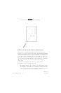
FIGURE 2-14 CONNECTOR PIN LOCATIONS shows the KRA 405B R/T mating
connector pin connections and the KNI 415/416 mating connector pin
locations. Refer to FIGURE 2-17 KRA 405B RADAR ALTIMETER SYSTEM
INTERCONNECT as required.
During preparation of the wiring harness, the following precautions
should be acknowledged:
• Bond and shield all parts of the aircraft electrical system such
as generators and ignition systems.
• Keep the cables away from circuits carrying heavy current, pulse-
transmitting equipment, 400 Hz circuits, and other sources of in-
terference.
• Make all external connections of the equipment through designated
connectors listed on the diagram.
• Wire size is specified on the interconnect diagram.
• Leave slack in cables to allow for free sway of the equipment.
• After installation of the cables in the aircraft and before in-
stallation of the equipment, a check should be made to ensure
that the aircraft power is applied only to the pins specified.
H. CONFIGURATION MODULE INSTALLATION
The KRA 405B interfaces to the CM 2000 Configuration Module.
The configuration module is an option that is only needed for
installations that require the trip points to be set to a value other
than the factory settings, or for installations requiring a zero
feet offset. Negative values cannot be displayed by EFIS 40/50
indicators when interfaced to the radar altimeter via ARINC 429.
The maximum cable length between the configuration module and the
KRA 405B shall not exceed two (2) feet.
NOTE: It is desirable to keep this cable length as short as pos-
sible.
Refer to FIGURE 2-18 CM 2000 CONFIGURATION MODULE MOUNTING DRAWING
for the CM 2000 mounting dimensions.