


N
KRA 405B RADAR ALTIMETER INSTALLATION MANUAL
Page 2-7
006-10536-0010 Rev. 10 Oct/2005
The selected mounting location will vary with each particular type
of aircraft. The unit should be installed in a convenient location
for accessibility for inspection and maintenance. The area should
be free from excessive vibration, heat, and noise generating
sources. The equipment and connecting cables must not interfere
with aircraft controls and other equipment.
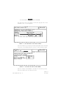
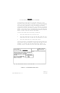
(1) Refer to FIGURE 2-6 KRA 405B INSTALLATION DRAWING for the KRA
405B R/T mounting dimensions.
a. For tray mounted units perform the following steps:
1. Mark, punch, then drill mounting holes, being
careful not to damage adjacent equipment or ca-
bles.
2. Using four (4) #6-32 screws, secure the mounting
tray in the position selected. The fluted knob
on the mounting tray should face in a direction
to provide easy access.
3. Slide the KRA 405B R/T into the rack. Secure the
unit in place by hooking the triangular keeper
over the front lip of the unit and tightening the
fluted knob.
b. For shock mounted units perform the following steps:
1. Mark, punch, then drill mounting holes, being
careful not to damage adjacent equipment or ca-
bles.
2. Secure shock mounts to airframe.
3. Using four (4) #6-32 screws, secure the unit in
the shock mounts.
4. For shock mounted units, solid metal straps shall
be used for bonding. Straps shall be short and
broad, with a length-to-width ratio under five
(5) to minimize impedance. Solid copper straps
shall be a minimum of 0.025 inches thick and
greater than 1 inch wide. Solid aluminum straps
shall be a minimum of 0.040 inches thick.