


N
KRA 405B RADAR ALTIMETER INSTALLATION MANUAL
Page 2-11
006-10536-0010 Rev. 10 Oct/2005
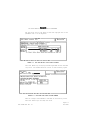
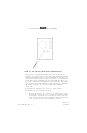
• Antennas should be pointing straight down within plus or minus
6° when the aircraft is in a level flight attitude. Antennas
mounted more than 6° off the vertical will exhibit erratic op-
eration on the ground. See FIGURE 2-7 DUAL RADAR ALTIMETER SYS-
TEM TYPICAL ANTENNA INSTALLATIONS for examples of this type of
installation.
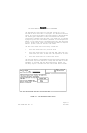
• Antennas may be mounted in-line or side-by-side. The in-line
mounting is the preferred choice of the two. When using side-
by-side installations, the antennas should be mounted on a flat
surface of the aircraft. The angle between the antenna center-
lines should be less than 6° .
Failure to correctly position antennas will result in erratic op-
eration on the ground, i.e., the needle will fluctuate as much
as 20 feet, dependent upon the angle between centerlines. Air-
borne operation will be satisfactory.
• Antennas should be mounted no less than 20 inches apart (measure
from center to center) in order that leakage between the antennas
remains at a tolerable level. The pointer may not stow above
2500 feet if the leakage between the antennas is too great.
• Antennas should not be separated by a distance greater than the
antenna height above the terrain at touchdown. If the antennas
are separated by more than this distance, sufficient terrain area
is not illuminated for ground level operation.
• The antennas should be mounted closer than the antenna height
above the terrain (but no less than 20 inches) if the angle be-
tween the antennas is greater than 6° .
• Antenna locations should provide 120° clearance cones. No air-
craft projection or other antenna should lie within these cones.
A fixed object in the cone could cause the altimeter to lock on
to a single altitude while a moving projection (gear, flaps,
etc.) could cause erratic operation.
• Surface area between antennas should be free from seams or other
discontinuities. NEVER mount an antenna directly on a seam. If
antennas must be separated by a seam, make sure that the two piec-
es of aircraft skin are electrically bonded together by adding
bonding straps (i.e., have multiple straps across seam separating
the two antennas).
Failure to bond properly can cause loss in system sensitivity
and/or cause the pointer to momentarily come into view above 2500
feet AGL (this phenomenon is commonly called "peeking").