


Contents
Revision 6 HercuLine™ 2000 Series Actuator - Installation, Operation and Maintenance Manual ix
7/07
Figures
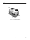
Figure 1 HercuLine
®
2000 Series Actuator .................................................................................................................2
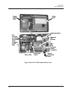
Figure 2 HercuLine
®
2002 Actuator Internal View.....................................................................................................3
Figure 3 Outline and Dimensions of HercuLine
®
2000 Series Actuators.................................................................14
Figure 4 Constant Torque Linkage ........................................................................................................................... 15
Figure 5 Variable Torque Linkage ............................................................................................................................16
Figure 6 Standard crank arm......................................................................................................................................16
Figure 7 Crank arm with optional ball joint and push rod......................................................................................... 16
Figure 8 HercuLine
®
2000 connections..................................................................................................................... 18
Figure 9 HercuLine
®
2001/2002 connections............................................................................................................ 19
Figure 10 HercuLine
®
2003 connections ..............................................................................................................20
Figure 11 CE wiring part 1....................................................................................................................................... 21
Figure 12 CE Wiring part 2 .......................................................................................................................................22
Figure 13 Burner Control/Flame Safety Wiring ....................................................................................................... 23
Figure 14 Series 90 connections ................................................................................................................................24
Figure 15 T775 Controller connections.................................................................................................................... 25
Figure 16 Flow Diagram............................................................................................................................................ 27
Figure 17 Interconnection Diagram........................................................................................................................... 27
Figure 18 Proportional Flow Using Multiple Actuators............................................................................................ 28
Figure 19 Multiple Actuator Interconnection Diagrams............................................................................................ 29
Figure 20 Interconnection Diagrams .........................................................................................................................30
Figure 21 HercuLine
®
2000 Display and Keypad .....................................................................................................31
Figure 22 Relay connectors .......................................................................................................................................46
Figure 23 Regions of Motor Travel ........................................................................................................................... 62
Figure 24 Auto - Manual Switch ...............................................................................................................................64
Figure 25 Calibration Wiring Connections (non-slidewire emulation) .....................................................................66
Figure 26 Calibration Wiring Connections (slidewire emulation)............................................................................. 67
Figure 27 Jumper Location on CPU PWA ............................................................................................................... 68
Figure 28 Location of NCS Assembly....................................................................................................................... 75
Figure 29 Location of potentiometer position sensor ................................................................................................77
Figure 30 End of Travel Limit Switch Settings......................................................................................................... 78
Figure 31 Location of End-of-Travel Limit and Auxiliary Switches ........................................................................80
Figure 32 Auxiliary Switch Settings.......................................................................................................................... 81
Figure 33 Terminal Block Connections for Modbus Communications..................................................................... 86
Figure 34 Spur Gear Location ...................................................................................................................................88
Figure 35 Power Distribution PWA and Relay PWA Locations............................................................................... 89
Figure 36 Motor Drive Circuit Fuses......................................................................................................................... 90
Figure 37 Replacement Kits 6, 7, 8, 11, 12, 14.......................................................................................................... 91
Figure 38 Replacement Kit 10.................................................................................................................................. 92
Figure 39 Replacement Kits 1, 2, 3, 4, 5, 9, 15, 16, 19.............................................................................................. 93
Figure 40 Replacement Kit 13...................................................................................................................................94
Figure 41 Replacement Kits 17, 18 ...........................................................................................................................95
Figure 42 Test for Actuator Operation ....................................................................................................................107
Figure 43 Power Up Diagnostics.............................................................................................................................108
Figure 44 Test Power Distribution PWA................................................................................................................. 109
Figure 45 Test AUTO - MANUAL Switch............................................................................................................. 110
Figure 46 Test Relay Function ................................................................................................................................111