


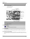
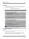

Burner Control/Flame Safety
Master/Slave Arrangement
30 HercuLine™ 2000 Series Actuator - Installation, Operation and Maintenance Manual Revision 6
7/07
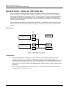
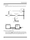
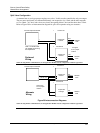
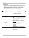
Split Valve Configuration
A common heat or cool type process requires two valves. In this case the controller has only one output.
The two motor positioners are calibrated differently, one responds to 4 to 12mA and the other responds
to 12 to 20mA. At 12mA, both valves are closed; one opening below 12mA and the other above 12mA.
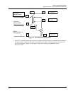
Refer to
Figure 20 for an interconnection diagram for split valve operation using two actuators.
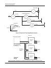
Hot
10260S Series Actuator #1
Neutral
Ground
120/240
VAC
250 Ohms
1 to 5 VDC
+
-
Current Output Controller
4 to 20 mA
Hot
10260S Series Actuator #2
Neutral
Ground
120/240
VAC
250 Ohms
1 to 5 VDC
Preferred
Wiring
Note: Controller must
be capable of sourcing
the impedance.
NOTE: If using HART
®
communications, for this application HART
®
must be configured for Multi-drop operation.
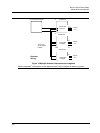
Hot
10260S Series Actuator #1
Neutral
Ground
120/240
VAC
250 Ohms
1 to 5 VDC
+
-
Current Output Controller
4 to 20 mA
Hot
10260S Series Actuator #2
Neutral
Ground
120/240
VAC
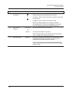
Alternate
Wiring
Figure 20 Interconnection Diagrams
NOTE: If using HART
®
communications, for this application HART
®
must be configured for Multi-drop operation.
Actuator #1
Actuator #2
Actuator #1
Actuator #2
Jumper W2
= Current
Jumper W2
= Current
Jumper W2
= Current
Jumper W2
= Voltage
See Figure
27 for jumper
location
See Figure
27 for jumper
location