


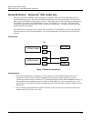
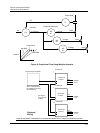
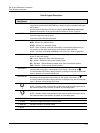

Burner Control/Flame Safety
Master/Slave Arrangement
28 HercuLine™ 2000 Series Actuator - Installation, Operation and Maintenance Manual Revision 6
7/07
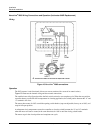
Proportional
with Bias
Ratio
Position
mA
PV
SP
4 to 20 mA
Controller
Positioner & Actuator
Linkage
Valve
Orifice Plate
FT
MP
#1
MP
#2
MP
#3
FIC
Linkage
Linkage
Valve
Valve
Figure 18 Proportional Flow Using Multiple Actuators
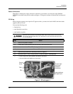
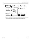
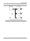
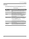
Hot
10260S Series Actuator #1
Neutral
Ground
120/240
VAC
250 Ohms
1 to 5 VDC
+
-
Current Output Controller
4 to 20 mA
Hot
10260S Series Actuator #2
Neutral
Ground
120/240
VAC
250 Ohms
1 to 5 VDC
Hot
10260S Series Actuator #3
Neutral
Ground
120/240
VAC
250 Ohms
1 to 5 VDC
Preferred
Wiring
Note: Controller must
be capable of sourcing
the impedance.
NOTE: If using HART
®
communications, for this application HART
®
must be configured for Multi-drop operation.
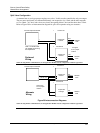
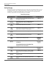
Actuator #1
Actuator #2
Actuator #3
Jumper W2
= Current
Jumper W2
= Current
Jumper W2
= Current
See Figure
27 for jumper
location