


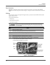
Installation
Electrical Installation
18 HercuLine™ 2000 Series Actuator - Installation, Operation and Maintenance Manual Revision 6
7/07
HercuLine
®
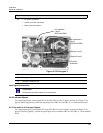
2000 Terminal Connections
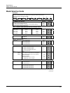
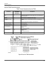
Table 3 Terminal Connections: HercuLine
®
2000
Connection
Terminal Numbers
and LABEL
See Figure 8
Descriptions
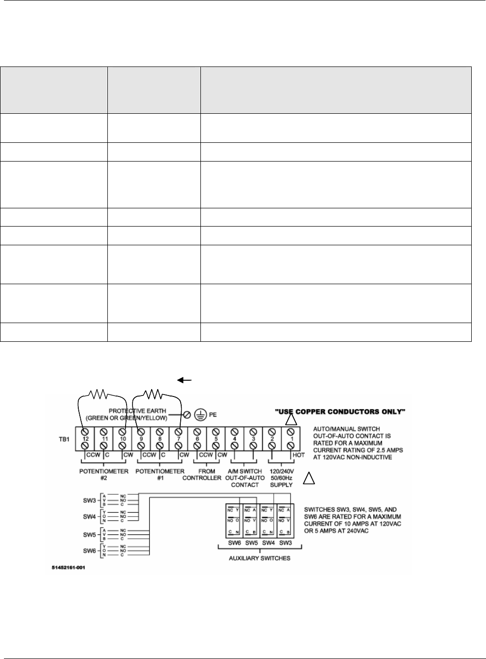
Hot 1
Hot wire for 120/240VAC mains supply. Use only if Auto/Manual
switch is present.
Neutral 2 Neutral wire for 120/240VAC mains supply
Auto/Manual Switch
Contact
3
4
Switch contact to indicate setting of actuator AUTO/MANUAL
switch.
Switch is closed when actuator is “NOT-IN-AUTO”
CW from Controller 5 CW motor drive
CCW from Controller 6 CCW motor drive
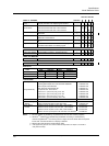
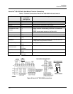
Potentiometer #1
7
8
9
Clockwise-End
Slider
Counterclockwise-End
Potentiometer #2
10
11
12
Clockwise-End
Slider
Counterclockwise-End
Protective Ground Ground wire connection for mains supply
158 ohm 158 ohm Install resistors to convert 1000 ohm
potentiometer to 135 ohms
1
1
REQUIRED ONLY IF AUTO/MANUAL
SWITCH IS PRESENT
158 ohm 158 ohm Install resistors to convert 1000 ohm
potentiometer to 135 ohms
11
11
REQUIRED ONLY IF AUTO/MANUAL
SWITCH IS PRESENT
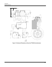
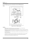
Figure 8 HercuLine
®
2000 connections