


Page 10 For technical questions, please call 1-800-444-3353. Item 90154
SAFETY OPERATION MAINTENANCEASSEMBLY
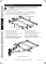
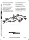
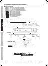
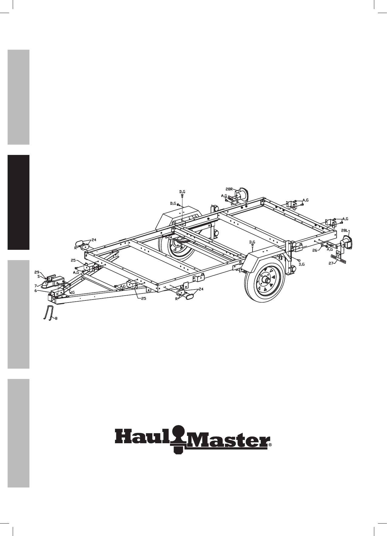
24. Attach the Coupler (7) to the Coupler Base (6),
using one M10x90 Bolt (W) at the rear of the coupler.
Lock the Coupler Trigger with the Lock Pin (29).
Then, insert the “R” Pin (S) through the
hole in the Lock Pin (29) to secure the
Lock Pin in place. (See Figure I.)
25. Insert the second M10x90 Bolt (W) through
the Coupler (7) and Coupler Base (6) as well
as through the center link of the Safety Chain.
Then,usea3/8″LockNut(G)tosecure
the Safety Chain to the Hitch Coupler.
26. Attach two Stake Clamps (25) to
the Front Cross Member (2A),
using M10x20 Bolts (A) and M10 Lock Nuts (G).
Then, repeat this Step for the remaining two
Stake Clamps and the Rear Cross Member (2B).
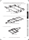
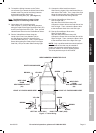
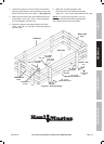
27. Remove the Lens from a Side Running Light (24).
Insert the Wire Lead of the
Side Running Light through the center
hole of the Front Left Side Rail (1FL).
Attach the Side Running Light to the
Front Left Side Rail, using the Screws (R).
Then, reattach the Lens to the Side Running Light.
Repeat this Step for the remaining Side Running
Light and the Front Right Side Rail (1FR).
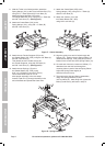
28. Attach a Tail Light Bracket (26) to the
Rear Left Side Rail (1RL), using M10x20 Bolts (A)
and M10 Lock Nuts (G). Attach the
License Plate Bracket (27) and Left Tail Light (28L)
totheTailLightBracket,using3/8″LockNuts(G).
Repeat this Step for the remaining Tail Light Bracket
and Rear Right Side Rail (1RR).
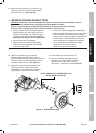
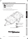
29. Secure the rear Bed of the Trailer’s frame
to the Caster Bases (30L, 30R), using
M10x30 Carriage Bolts (D) and M10 Lock Nuts (G).
Figure I: Coupler and Stake Clamp Attachment