


GEK-95352
9
Power supply phase-sequence rever-
sal will also cause the motor to re-
verse and unscrew the pump shaft,
but this rarely occurs. An anti-
phase-reversal relay can be incorpo-
rated in the motor controller if de-
sired.
To prevent uncoupling on initial
start-up, check motor rotation direc-
tion before installing the upper half-
coupling to be sure direction is cor-
rect. To reverse direction of rota-
tion, interchange any two power
leads.
2. Bolted Couplings
Bolted couplings allow up-thrust
from the pump to be taken by the
motor bearings. This type of cou-
pling is similar to a self-release
coupling except that the driving pins
are replaced by bolts, which should
be securely tightened to hold the
two halves of the coupling solidly
together so that torque is transmitted
by face friction. See torque re-
quirements. This type of coupling
does not have the self-release fea-
ture and allows reverse rotation.
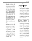
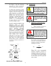
See the self-release coupling shown
to the left of the motor centerline in
Figure 1, which is applicable to
bolted couplings except that the
headless drive pins are replaced by
bolts as explained above.
4. Non-Reverse Couplings
The non-reverse type of coupling, as
shown to the right of the motor
centerline in Figure 1, is also a
bolted type, and, in addition, it
keeps the pump and motor from ro-
tating in the reverse direction. Thus,
it not only prevents the pump shaft
from unscrewing, but it also pre-
vents damage from overspeeding
and damage to water-lubricated
pump shaft bearings, when during
shutdown the residual water in the
system drives the pump in the re-
verse direction. This type of cou-
pling also allows up-thrust from the
pump to be carried by the motor
bearings. Motor torque is transmit-
ted to the pump shaft through the
two halves of the coupling which
are bolted together. See required
bolt torques.
The operation of a non-reverse cou-
pling is explained as follows. When
the motor is started in the correct or
forward direction, the ratchet pins
are lifted by the ratchet teeth, and
are held up by centrifugal force and
friction when motor speed becomes
high enough. When power is re-
moved, the speed decreases, and the
pins fall. At the instant of reversal, a
pin will catch on a ratchet tooth and
prevent backward rotation. The
number of pins differ from the
number of teeth to multiply the
number of stopping positions.
A very rapid decrease in speed can
result in acceleration forces great
enough to prevent the pins from
dropping. This condition is further
aggravated when the pins become
dirty, and their action sluggish. If
the time from shutdown (the instant
the “stop” button is pressed) to zero
speed is greater than two seconds,
operation will be satisfactory.
To permit operation when stopping
time is less than two seconds, the
pins are spring-loaded. For those
cases involving cycling (frequent
starting and stopping) and stopping
times greater than two seconds, the