


GEK-95352
7
The SYSTEM REED CRITICAL
FREQUENCY should be 25% above or
below motor operating speed in order to
avoid excessive vibration.
C. Alignment of Solid-Shaft Motors
Accurate mechanical lineup is essential
for successful operation. Mechanical vi-
bration and roughness when the motor is
running may indicate poor alignment. In
general, lineup by straight edge across,
and feeler gages between coupling halves
is not sufficiently accurate. It is recom-
mended that the lineup be checked with
dial indicators. The space between cou-
pling hubs should be maintained as rec-
ommended by the coupling manufacturer.
D. Couplings for Hollow-Shaft
Motors
1. General
Vertical hollow-shaft motors are
designed for driving deep-well, tur-
bine-type pumps and can be
equipped with either self-release,
bolted, or non-reverse couplings as
described in following sections.
These couplings are located at the
top of the motor and allow pump
impeller position to be adjusted eas-
ily. The type of coupling is specified
by the customer. Remove the top
cap for access to the coupling.
Two slots are provided in the out-
side rim of the coupling so that a bar
can be inserted to keep the assembly
from turning while the adjustment
of pump impeller clearance is being
made. A coupling bolt can be
screwed into one of the extra tapped
holes in the top endshield to provide
a stop for the bar.
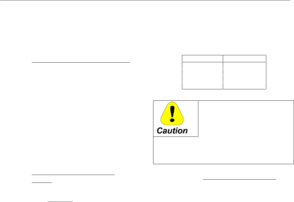
To prevent breakage, coupling bolts
must be tightened to torque values
indicated below for bolted or non-
reverse couplings
Bolt Size Torque
1/2 90 lb-ft
5/8 180 lb-ft
3/4 320 lb-ft
1 710 lb-ft
It shall be the installer’s re-
sponsibility in all cases to as-
certain that these torque values
are used and maintained. This
shall include those instances
when the coupling comes mounted in the mo-
tor. Failure to comply may cause the coupling
bolts to break, with resultant extensive damage
to the equipment.
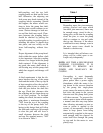
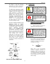
2. Self-Release Couplings
Should the motor accidentally be
run in the reverse direction, the
pump line-shaft joints may unscrew.
The self-release coupling acts to
limit the amount of this unscrewing.
In normal operation, torque from the
motor is transmitted by the lower
half-coupling through the driving
pins to the upper half-coupling, and
then to the pump shaft. If reversal
occurs and the pump shaft starts to
unscrew and lengthen, the upper
half of the self-release coupling is
lifted up off of the driving pins, thus
uncoupling the pump from the mo-
tor. See Figure 1, where a self-
release coupling is shown to the left
of the shaft center-line.
NOTE : THAT SELF-RELEASE COU-
PLINGS CANNOT CARRY UP-
THRUST
Proper functioning of a self-release
coupling depends upon several fac-
tors. The pump shaft adjusting nut
must be securely attached to the top