


GEK-95352
8
half-coupling, and the top half-
coupling must not bind on the lower
half. Otherwise, the adjusting nut
lock-screw may break instead of the
coupling halves separating. Should
this happen, the motor would con-
tinue to drive the pump line shaft,
and the joints would continue to un-
screw. Serious damage to both mo-
tor and line shaft may result. Clear-
ance between the coupling halves
should be checked by placing the
top half-coupling in position prior to
installing the motor. It should drop
into place, and rest solidly on the
lower half-coupling, without forc-
ing.
Proper alignment of the pump head-
shaft within the motor hollow shaft
is also important. After the coupling
releases it no longer holds the pump
shaft centered. If the alignment is
not good, the motor shaft which is
still rotating may rub the pump shaft
which has stopped, and damage will
result.
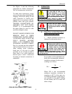
A third requirement is that the dis-
tance between the top of the pump
shaft and the inside of the top cap be
at least enough to allow the top half-
coupling, when it tries to release, to
clear the pins before the shaft hits
the cap. Check this clearance after
the adjusting nut has been drawn up
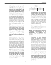
to its final position. To facilitate
making the check, the motor outline
print shows a maximum dimension
"XH" from the top of the coupling
to the top of the pump shaft. Ad-
hering to this design limit will allow
the shaft and coupling to lift enough
to clear the pins and still leave a
small clearance between the shaft
and cap. For standard motors, “XH”
is as shown in Table 1.
Table 1
Frame Size XH
444-449 4.38”
509-5011 4.88”
Depending upon the circumstances
causing reversal and upon which
line-shaft joint unscrews, there may
be enough energy stored in the ro-
tating parts, at the time the coupling
clears the pins, to cause the pump
shaft to continue to rise and strike
the top cap. However, if the above
conditions are met, damage, even in
the most severe cases, should be
limited to a broken cap.
It is intended that self-release cou-
plings will be called upon to un-
couple only infrequently.
NOTE: ANY TIME A SELF-RELEASE
COUPLING UN-COUPLES, IT IS
NECESSARY T0 REMOVE ALL
POWER AND MANUALLY RE-
COUPLE.
Uncoupling is most frequently
caused by application of single-
phase power after a power supply
disturbance, while the motor is be-
ing driven in the reverse direction
by the pump; this single-phase
power causes the motor to take over
and drive the pump in the reverse
direction and the pump shaft joints
will then unscrew. To prevent this,
select a motor starter which requires
a manual start after any stop (rather
than allowing automatic re-start as
soon as power is applied to the
starter), or incorporates a back-spin
timer to keep power from being
automatically reapplied to the motor
until enough time has elapsed for
water back-flow through the pump
to stop and for the motor to com-
pletely stop.