


GEK-95352
19
line up. Turning the nut from one
locking position to the next repre-
sents a change of end-play of ap-
proximately 0.0028”.
When run uncoupled from the
pump, the motor may have exces-
sive vibration. If so, it should be
checked with zero end-play. The
thrust bearing will then be more
nearly in the position it will assume
when down-thrust is applied during
normal operation. After the check
run, set the end-play as described
previously. Do not run motors with
spherical roller thrust bearings un-
coupled for long periods because the
lower bearing may over-heat or fail
because of the up-thrust load im-
posed by the springs.
F. Bearing Replacement
In general, replacement bearings should
be of the same type, and installed in the
same relative position, as the original
bearings.
When removing bearings, apply steady,
even pressure parallel to the shaft or
lower half-coupling center-line. Apply
this pressure to the inner race whenever
possible. Angular-contact bearings which
have failed, and are especially tight on the
coupling, can sometimes be removed by
using the following procedure: separate
the bearing by forcing the outer race over
the balls; then with a torch, apply quick
heat to the inner race while also applying
pulling pressure.
Angular-contact bearings which are to be
stacked together should have their high
points of eccentricity (indicated by a bur-
nished spot on the inner race) lined up.
All bearings should be of same manufac-
ture and of the type that permits stacking.
Some motors with angular-contact ball
bearings are supplied with removable
spacer ring under the outer race of the
thrust bearing so that the thrust capacity
can be increased by adding an extra
bearing or bearings. When these bearings
are installed, the high points of eccentric-
ity should be lined up with the keyway in
the lower half-coupling. If the original
bearings have been in service, they should
be replaced at the time this conversion is
made.
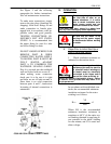
G. Oil Cooling Coil Maintenance
See general description of cooling coil
connection fitting and Figure 4.
As part of ongoing preventative mainte-
nance check for oil leaks around the
cooling coil fitting, and check for possible
internal water leakage as indicated by an
unexplained rise in oil level or a change
in oil color. Parts A, B, E and F should
always be tight, and part B should always
be seated tightly against part A to ensure
that the sealing O-Ring is properly com-
pressed.
If cooling coil is to be removed, first re-
move supply pipes and drain water out of
coil. Next remove parts F, B, E and A in
that order. Then remove the endshield
cover and unscrew the inlet and outlet
pipes (part C) from the cooling coil being
careful to hold the elbows on the ends of
the cooling coil to prevent damage. Fi-
nally, remove the oil-baffle and the cool-
ing coil.
To re-install the cooling coil proceed as
follows:
1. OBTAIN A NEW O-RING
UNLESS YOU ARE CERTAIN
OLD O-RING IS UN-DAMAGED
AND HAS NOT AGED OR
TAKEN A COMPRESSION SET.