


GEK-95352
17
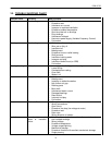
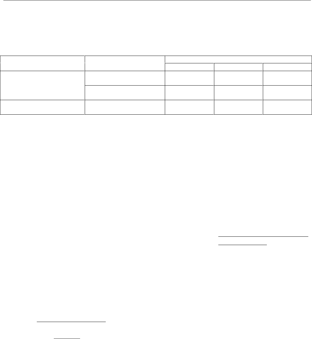
TABLE II
OIL VISCOSITY
(For a particular motor, refer to the lubrication nameplate or instructions.)
Bearing Function Oil Viscosity - SUS
and Location Bearing Type
@100°F@°210 F
GE Spec
Thrust Bearing Angular Contact Ball 150 45 D6B6A
(In top endshield) Spherical Roller 600 70 D6B14C1
or 300 53 D6B6B
Guide Bearing Ball 150 45 D6B6A
(In base endshield)
Oil-lubricated bearing housings are pro-
vided with large settling chambers in
which dust, dirt, and sludge collect. Un-
less the oil has been permitted to oxidize,
the draining of the old oil during regular
changes will usually provide sufficient
flushing action to clean out the reservoir.
Whenever the motor is disassembled for
general cleaning and reconditioning, the
bearing housing may be washed out with
a suitable cleaning solvent. 1,1,1 Trichlo-
roethane may be used, following the same
instructions and cautions as shown for
cleaning windings. Avoid using any sol-
vent that will soften the paint used on the
interior of’ the oil reservoir. Be sure that
the oil metering hole is clear, and then dry
the housing thoroughly before reassem-
bly.
E. End-Play Adjustment
1. General
Most high-thrust motors are de-
signed to withstand only momentary
up-thrust. This up-thrust, which can
exist for a few seconds during
starting, is taken by the lower guide
bearing. To prevent the thrust bear-
ing from losing radial stability dur-
ing this time, the motor end-play is
limited to a small amount by ad-
justment of the motor shaft nut. This
adjustment is made at the factory
and need not be disturbed on a new
motor. However, should the motor
be disassembled for any reason, the
adjustment must be made during re-
assembly to avoid damaging the
bearings, or having some rotating
part rub against a stationary part.
The procedure depends upon the
type of thrust bearing.
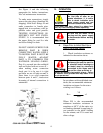
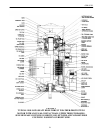
2. End-Play Adjustment – Ball
Thrust Bearing
For a motor with angular-contact
ball thrust bearings, refer to Figure
1. When the motor shaft nut is tight-
ened, the rotor, shaft, and lower
bearing are drawn up until the outer
ring of the lower bearing seats
against the lower bearing cover.
Further tightening of the nut pre-
loads the bearings. (Note that shoul-
der on the shaft below the lower
half-coupling is purposely located
so that it does not seat against the
coupling.)
The best way to adjust the nut is by
trial, using an indicator between the
lower half-coupling and top end-
shield, and lifting the rotor to check
the end-play after each setting of the
nut until between 0.002 and 0.005”