


GEK-95352
10
springs may be removed to decrease
wear on the ratchet plate.
Pins and springs are made of heat-
treated stainless steel.
A complete non-reverse coupling
consists of a self-release coupling
plus a non-reverse assembly, which
includes pin carrier, pins, springs,
pin retaining plate, and cap-screws.
On motors covered by this instruc-
tion book, the ratchet teeth are an
integral part of the endshield cover
casting.
A self-release or a bolted coupling
can be converted to a non-reverse
coupling without disturbing the ad-
justment of the pump shaft nut. The
non-reverse aAssembly will nor-
mally be received as a unit. To as-
semble it onto the motor, loosen the
3 small capscrews that hold the pin-
retaining plate so this plate can be
centered during assembly. Next, re-
move the drive-pins or bolts from the
lower half-coupling. Then slide the
non-reverse assembly down over the
top half-coupling. Next insert the
long cap screws through the plate,
pin carrier, and top coupling and into
the lower coupling. Tighten them
securely so that torque will be trans-
mitted by friction between the cou-
pling faces rather than through the
bolts. See TORQUE REQUIRE-
MENTS. Finally tighten the 3 small
capscrews to secure the pin-retaining
plate.
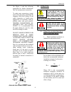
The top half of the coupling should
seat solidly on the lower half and
the pins should touch the bottom of
the pockets between the teeth in the
ratchet. The clearance between the
pin-carrier and the top of the ratchet
teeth should be between 1/16 and
1/8”.
When installing a non-reverse
coupling do not use lubricant. Lu-
brication will lower the coefficient
of friction between pins and pin-
carrier, and the pins may not stay up
when motor reaches full speed.
Motors shipped from stock may
have their top couplings and non-
reverse assemblies packaged sepa-
rately. They can be installed as de-
scribed in previous paragraphs.
E. Power Supply Connections
1. Wiring and Grounding
Motor and control wiring, over-
load protection, and grounding
should be in accordance with
the National Electrical Code and
consistent with sound local
practices. Failure to observe
these precautions may result in damage to the
equipment, injury to personnel, or both.
Stator winding connections should
be made as shown on the connection
diagram or in accordance with the
wiring diagram attached to the in-
side of the conduit box cover. For 3-
lead motors no connection diagram
is needed or supplied.
The motor frame may be grounded
by attaching a ground strap from a
known ground point to the bronze
grounding bolt in the conduit box.
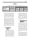
2. Allowable Voltage and
Frequency
The power supply must agree with
the motor nameplate voltage and
frequency. Motors will operate (but
with characteristics somewhat dif-
ferent from nameplate values) on
line voltages within + l0% of name-
plate value or frequency within