


59
APPENDIX C
Specifications &
Wiring
NMEA 0180, NMEA 0182,
NMEA 0183 version 1.5:
Approved sentences:
GPBWC, GPGLL, GPRMB, GPRMC, GPXTE,
GPVTG, GPWPL, GPBOD
Proprietary sentences:
PGRMM (map datum), PGRMZ
(altitude), PSLIB (beacon rec. control)
NMEA 0183 version 2.0:
Approved sentences:
GPGGA, GPGLL, GPGSA, GPGSV,
GPRMB, GPRMC, GPRTE, GPWPL, GPBOD
Proprietary sentences:
PGRME (estimated error), PGRMM (map
datum), PGRMZ (altitude), PSLIB (beacon
receiver control)
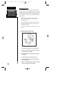
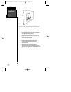
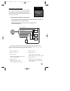
Connecting the power/data cable
The power/data cable connects the GPS 126/128 sys-
tem to a 10-40 volt DC power source and provides inter-
face capabilities for connecting NMEA devices and an
external alarm The diagram below indicates the appropri-
ate harness connections.
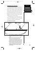
To connect the GPS 126/128 to a power source:
1. Connect the RED harness lead to the positive side of a 10-40 volt DC power source. Make sure
the power lead has an in-line 1-amp fuse installed.
2. Connect the BLACK harness lead to a ground strip or the negative side of a
10-40 volt DC power source.
To connect an external alarm, connect the ground side of the alarm device to the
YELLOW harness lead. (100 mA DC load max.) The following interface formats are sup-
ported by the GPS 126/128 for driving three NMEA devices:
PIN 1 (red): 10-40 volts DC
PIN 2 (black): Ground
PIN 3 (blue): NMEA out
PIN 4 (brown): NMEA in
PIN 5 (white): No connection
PIN 6 (green): No connection
PIN 7 (yellow): alarm low
1
2
3
4
5
6
7
Pin assignment
(-) (+)
10-40 volts DC
Autopilot/
NMEA Device
GBR 21
Beacon
Receiver
Alarm/
Relay
(-)
Shield Grounded
Through GPS
(+)
126/128 Manual (new) 6/15/98 9:52 AM Page 59