


SP - 2
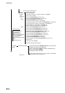
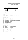
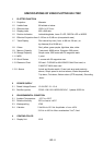
3 TRANSCEIVER MODULE
3.1 Frequency and Modulation 9410 MHz ±30MHz (X band), P0N
3.2 Peak Output Power M1724C: 2 kW nominal,
M1734C: 4 kW nominal,
3.3 Modulator FET Switching Method
3.4 Intermediate Frequency 60 MHz
3.5 Tuning Automatic
3.6 Receiver Front End MIC (Microwave IC)
3.7 Bandwidth 7 MHz
3.8 Duplexer Circulator with diode limiter
3.9 Warming up M1724C: 60 s approx, M1734C: 90 s approx.
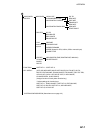
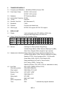
4 DISPLAY UNIT
4.1 Display 7-inch rectangular color LCD, 480(H) x 640(V) dots,
Effective radar display area: 432 x 432 mm
4.2 Range, Range Ring Interval (RI), Number of Rings
Range (nm) 0.125 0.25 0.5 0.75 1 1.5 2 3 4 6 8 12 16 24 36
RI (nm) 0.0625 0.125 0.125 0.25 0.25 0.5 0.5 1 1 2 2 3 4 6 12
Rings 2 2 4 3 4 3 4 3 4 3 4 4 4 4 3
Maximum range:
M1724C: 24nm, M1734C: 36nm
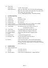
4.3 Markers Heading Line, Bearing Scale, Range Rings,
Variable Range Marker (VRM), Electronic Bearing Line (EBL),
Alarm Zone, Waypoint Mark (navigation input required)
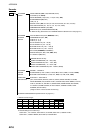
4.4 Alphanumeric Indications Range, Range Ring Interval, Interference Rejection (IR),
Variable Range Marker (VRM), Electronic Bearing Line (EBL),
Stand-by (ST-BY), Echo Averaging (EAV), TX Pulse width
Guard Alarm (G(IN), G(OUT)), Echo Stretch (ES),
Range and Bearing to Cursor or Cursor Position,
Echo Trailing (TRAIL), Trailing Time,
Data Box (Position, COG, SOG, STW, etc. selectable on menu)
4.5 Input Data IEC 61162-1 (NMEA 0183 Ver1.5/2.0)
Own ship’s position: GGA>RMC>RMA>GLL
Ship’s speed: RMC>RMA>VTG>VHW
Bearing (True): HDT>HDG
*1
>HDM
*1
Course: RMC>RMA>VTG
Water depth: DPT>DBT
Wind: MWV>VWT>VWR
Water Temperature: MTW
Time: ZDA
*1
: calculated by magnetic deviation