


windows (early models) and the tailgate
remote release mechanism, where fitted.
19 Disconnect the battery negative (earth)
lead (refer to Chapter 5A, Section 1).
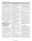
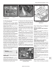
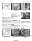
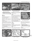
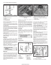
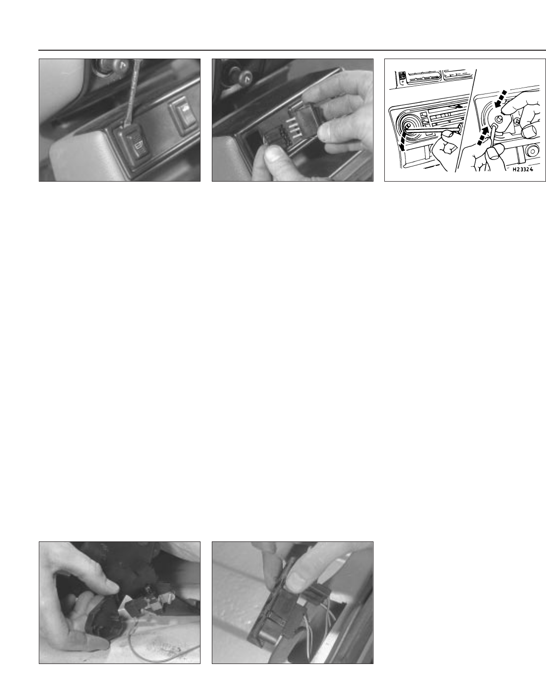
20 To remove a switch, carefully prise it from
its location using a thin flat-bladed
screwdriver, then disconnect the multi-plug
(see illustrations).
21 To refit, connect the multi-plug then push
home to secure.
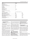
Heater fan motor control switch
22 Disconnect the battery negative (earth)
lead (refer to Chapter 5A, Section 1).
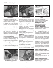
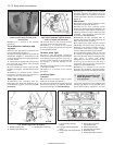
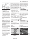
23 Pull the heater fan motor control knob off,
then move the air distribution and
temperature controls fully to the right. Unclip
and remove the heater slide facia towards the
left-hand side of the vehicle, removing the
slide control knobs only as necessary, and
disconnecting its bulbholder (bayonet type) as
it is withdrawn (see illustration).
24 Squeeze the two release tabs together on
the heater fan motor control switch, and
remove it, disconnecting its multi-plug as it is
withdrawn.
25 Refit by reversing the removal procedure.
Brake stop-light switch
26 The brake stop-light switch is attached to
the brake pedal mounting bracket.
27 Detach the wiring multi-plug from the
switch, then twist the switch through a quarter
of a turn (90º) anticlockwise and withdraw it
from the bracket.
28 Insert the switch into its retainer, press it
lightly against the brake pedal until all free
play is just taken up, then turn the switch
clockwise to secure. Reconnect the switch
wiring connector and the battery.
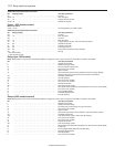
Handbrake warning light
switch
29 Push the carpet mounding down as
necessary to gain access to the switch,
located on the handbrake lever.
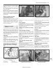
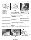
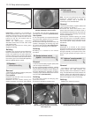
30 Remove the cover, then disconnect the
warning light switch wiring multi-plug (see
illustration). Undo the two screws securing
the switch to the handbrake lever assembly
and remove the switch.
31 Refit by reversing the removal procedure.
Low brake fluid level warning
light switch
32 This is incorporated into the brake fluid
reservoir cap, and senses fluid level in the
reservoir. It cannot be renewed separately
from the cap.
33 To remove, disconnect the warning
indicator loom multi-plug and unscrew the
reservoir cap.
34 Refit by reversing the removal procedure.
Courtesy light switches
35 Disconnect the battery negative (earth)
lead (refer to Chapter 5A, Section 1).
36 With the door open, undo the retaining
screw and withdraw the switch from the door
pillar. Pull out the wiring slightly, and tie a
piece of string to it, so that it can be retrieved
if it drops down into the door pillar.
37 Disconnect the wiring from the switch.
38 Refitting is a reversal of removal.
Reversing light switch
39 Refer to Chapter 7A, Section 6.
Starter inhibitor switch
(automatic transmission)
40 Disconnect the battery negative (earth)
lead (refer to Chapter 5A, Section 1).
41 The starter inhibitor switch is located on
the transmission housing, and prevents the
engine from being started with the selector
lever in any position except “P” or “N”.
Access to the switch is gained after raising
and supporting the vehicle at the front end on
axle stands (see “Jacking and vehicle
support”).
42 Detach the switch multi-plug, then
unscrew and remove the switch from the
transmission, together with its O-ring. As the
switch is removed, catch any fluid spillage in a
suitable container, and plug the switch
aperture in the transmission to prevent any
further loss.
43 Refitting is a reversal of the removal
procedure. Use a new O-ring, and tighten the
switch securely. Ensure that the wiring
connection is securely made. On completion,
check and if necessary top-up the automatic
transmission fluid (see Chapter 1) then check
that the engine only starts when the selector
is in the “P” or “N” position.
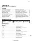
Luggage area contact plate
44 Disconnect the battery negative (earth)
lead (refer to Chapter 5A, Section 1).
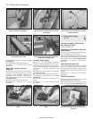
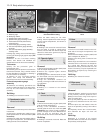
45 Open the tailgate and release the contact
plate side retaining clips using a thin-bladed
screwdriver. Push the contact plate from its
location in the body.
46 Disconnect the wiring multi-plug and
remove the plate (see illustration).
47 Refit in the reverse order of removal.
Luggage area contact switch
48 Disconnect the battery negative (earth)
lead (refer to Chapter 5A, Section 1).
49 Open the tailgate and remove its inner
trim panel (see Chapter 11).
12•6 Body electrical systems
4.46 Withdrawing the luggage area
contact plate for access to disconnect the
multi-plug
4.30 Removing the cover from the
handbrake warning light switch
4.23 Heater fan motor control switch
removal
4.20b . . . then disconnect its multiplug
and remove the switch
4.20a Prise the centre console switch up
from its location . . .
1595Ford Fiesta Remake