


the inside face of the cover to remove and fit
the fuses (see illustrations).
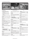
2 To remove a fuse, use the tweezers
provided to pull it out of the holder. Slide the
fuse sideways from the tweezers. The wire
within the fuse is clearly visible, and it will be
broken if the fuse is blown.
3 Always renew a fuse with one of an
identical rating. Never renew a fuse more than
once without tracing the source of the trouble.
The fuse rating is stamped on top of the fuse.
4 With the exception of the indicator flasher
relay, the remainder of the relays are fitted to
the reverse side of the main fuse/relay board.
Access is as described in paragraph 1.
5 The various relays can be removed from
their respective locations on the fuse board by
carefully pulling them from the sockets.
6 The direction indicator flasher relay is
attached to the multi-function switch unit on
the steering column. Access to the relay is
made by undoing the retaining screws and
removing the steering column shrouds. The
relay can then be withdrawn from the switch.
7 If a system controlled by a relay becomes
inoperative and the relay is suspect, listen to
the relay as the circuit is operated. If the relay
is functioning, it should be possible to hear it
click as it is energised. If the relay proves
satisfactory, the fault lies with the
components or wiring of the system. If the
relay is not being energised, then it is not
receiving a main supply voltage or a switching
voltage, or the relay is faulty.
4 Switches -
removal and refitting
2
Ignition switch (loom plate and
lock barrel)
1 Disconnect the battery negative (earth) lead
(refer to Chapter 5A, Section 1).
2 Remove the manual choke control knob,
where fitted, by depressing the lug securing it,
and pulling it from its shaft. The lug is found
on the side of the control knob shank.
3 Remove the lower steering column shroud
by undoing its four retaining screws, then
detach the choke warning light switch/pull
control assembly from the lower shroud by
unscrewing its retaining collar (bayonet-type
fixing), using a suitable tool to locate in the
collar recesses.
4 Remove the two screws securing the upper
steering column shroud from above, and the
two screws securing it from below, the latter
accessible only with the lower shroud
removed.
5 Disconnect the ignition switch wiring multi-
plug connector. Insert a thin-bladed
screwdriver into the lock tab aperture, release
the locking tab and remove the loom plate
from its location on the left-hand side of the
steering column.
6 Where applicable, undo the single screw
and withdraw the Passive Anti-Theft System
(PATS) transceiver from the ignition
switch/steering lock barrel.
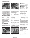
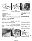
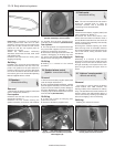
7 Insert the key and turn the ignition switch to
position ”I”. Depress the lock barrel plunger
through the steering column lock housing. As
the lock barrel plunger is depressed, pull
on the ignition key to remove the lock barrel
(see illustration).
8 Refitting is a reversal of the removal
procedure. When relocating the switch to the
steering lock, the barrel driveshaft must align
with the switch shaft as it is pushed into
position. Check the switch for satisfactory
operation on completion.
Steering column multi-function
switch
9 Carry out the operations described in
paragraphs 1 to 4 above.
10 Disconnect the wiring multi-plugs from
the multi-function switch assembly, then
remove the single screw securing the switch
assembly to the steering column lock
housing. This retaining screw is located
directly forward of the hazard warning light
switch. Remove the switch assembly.
11 Refitting is a reversal of the removal
procedure.
Facia centre panel switches
(below heater controls)
12 These switches individually control the
front and rear foglights, heated windscreen
and heated rear window element. Where
these features are not fitted to the vehicle,
blanking plates are installed instead of
switches.
13 Disconnect the battery negative (earth)
lead (refer to Chapter 5A, Section 1).
14 Remove the radio/cassette player as
described in Section 22.
15 Remove the ashtray, then undo the three
screws from the base of the centre panel.
Withdraw the centre panel, disconnecting the
cigarette lighter connections as it is
withdrawn.
16 Push the required switch/switches out
from behind, disconnect the multi-plug and
remove the switch.
17 Refitting is a reversal of the removal
procedure.
Centre console switches
18 The switches mounted on the centre
console control the electrically operated
Body electrical systems 12•5
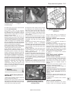
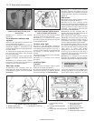
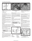
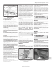
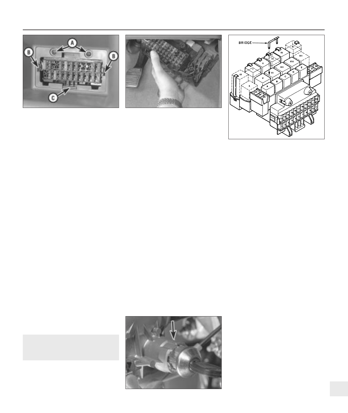
3.1c Component layout on the fuse/relay
board. See Specifications for relay
identification
3.1b Withdrawing the fuse/relay board
downwards into the driver’s footwell
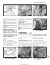
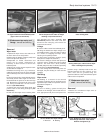
3.1a Method of fuse/relay board retention
A Retaining screws C Support
B Retaining lugs
4.7 Withdraw the lock barrel after
depressing its plunger through the
aperture in the steering column lock
housing (arrowed)
12
1595Ford Fiesta Remake