


wiring diagrams are included at the end of this
manual.
2 Before attempting to diagnose an electrical
fault, first study the appropriate wiring
diagram, to obtain a complete understanding
of the components included in the particular
circuit concerned. The possible sources of a
fault can be narrowed down by noting if other
components related to the circuit are
operating properly. If several components or
circuits fail at one time, the problem is likely to
be related to a shared fuse or earth
connection.
3 Electrical problems usually stem from
simple causes, such as loose or corroded
connections, a faulty earth connection, a
blown fuse, a melted fusible link, or a faulty
relay (refer to Section 3 for details of testing
relays). Visually inspect the condition of all
fuses, wires and connections in a problem
circuit before testing the components. Use
the wiring diagrams to determine which
terminal connections will need to be checked
in order to pinpoint the trouble-spot.
4 The basic tools required for electrical fault-
finding include a circuit tester or voltmeter (a
12-volt bulb with a set of test leads can also
be used for certain tests); an ohmmeter (to
measure resistance and check for continuity);
a battery and set of test leads; and a jumper
wire, preferably with a circuit breaker or fuse
incorporated, which can be used to bypass
suspect wires or electrical components.
Before attempting to locate a problem with
test instruments, use the wiring diagram to
determine where to make the connections.
Warning: Under no
circumstances may live
measuring instruments such as
ohmmeters, voltmeters or a bulb
and test leads be used to test any of the
air bag circuitry or components. Any
testing in these areas must be left to a
Ford dealer as there is a danger of
activating the system if the correct
procedures are not followed.
5 To find the source of an intermittent wiring
fault (usually due to a poor or dirty
connection, or damaged wiring insulation), a
“wiggle” test can be performed on the wiring.
This involves wiggling the wiring by hand to
see if the fault occurs as the wiring is moved.
It should be possible to narrow down the
source of the fault to a particular section of
wiring. This method of testing can be used in
conjunction with any of the tests described in
the following sub-Sections.
6 Apart from problems due to poor
connections, two basic types of fault can
occur in an electrical circuit - open-circuit, or
short-circuit.
7 Open-circuit faults are caused by a break
somewhere in the circuit, which prevents
current from flowing. An open-circuit fault will
prevent a component from working.
8 Short-circuit faults are caused by a “short”
somewhere in the circuit, which allows the
current flowing in the circuit to “escape” along
an alternative route, usually to earth. Short-
circuit faults are normally caused by a
breakdown in wiring insulation, which allows a
feed wire to touch either another wire, or an
earthed component such as the bodyshell. A
short-circuit fault will normally cause the
relevant circuit fuse to blow.
Finding an open-circuit
9 To check for an open-circuit, connect one
lead of a circuit tester or the negative lead of a
voltmeter either to the battery negative
terminal or to a known good earth.
10 Connect the other lead to a connector in
the circuit being tested, preferably nearest to
the battery or fuse. At this point, battery
voltage should be present, unless the lead
from the battery or the fuse itself is faulty
(bearing in mind that some circuits are live
only when the ignition switch is moved to a
particular position).
11 Switch on the circuit, then connect the
tester lead to the connector nearest the circuit
switch on the component side.
12 If voltage is present (indicated either by
the tester bulb lighting or a voltmeter reading,
as applicable), this means that the section of
the circuit between the relevant connector
and the switch is problem-free.
13 Continue to check the remainder of the
circuit in the same fashion.
14 When a point is reached at which no
voltage is present, the problem must lie
between that point and the previous test point
with voltage. Most problems can be traced to
a broken, corroded or loose connection.
Finding a short-circuit
15 To check for a short-circuit, first
disconnect the load(s) from the circuit (loads
are the components which draw current from
a circuit, such as bulbs, motors, heating
elements, etc).
16 Remove the relevant fuse from the circuit,
and connect a circuit tester or voltmeter to the
fuse connections.
17 Switch on the circuit, bearing in mind that
some circuits are live only when the ignition
switch is moved to a particular position.
18 If voltage is present (indicated either by
the tester bulb lighting or a voltmeter reading,
as applicable), this means that there is a
short-circuit.
19 If no voltage is present during this test,
but the fuse still blows with the load(s)
reconnected, this indicates an internal fault in
the load(s).
Finding an earth fault
20 The battery negative terminal is
connected to “earth” - the metal of the
engine/transmission and the vehicle body -
and many systems are wired so that they only
receive a positive feed, the current returning
via the metal of the car body. This means that
the component mounting and the body form
part of that circuit. Loose or corroded
mountings can therefore cause a range of
electrical faults, ranging from total failure of a
circuit, to a puzzling partial failure. In
particular, lights may shine dimly (especially
when another circuit sharing the same earth
point is in operation), motors (eg wiper
motors or the radiator cooling fan motor) may
run slowly, and the operation of one circuit
may have an apparently-unrelated effect on
another. Note that on many vehicles, earth
straps are used between certain
components, such as the engine/
transmission and the body, usually where
there is no metal-to-metal contact between
components, due to flexible rubber
mountings, etc.
21 To check whether a component is
properly earthed, disconnect the battery (refer
to Chapter 5A, Section 1) and connect one
lead of an ohmmeter to a known good earth
point. Connect the other lead to the wire or
earth connection being tested. The resistance
reading should be zero; if not, check the
connection as follows.
22 If an earth connection is thought to be
faulty, dismantle the connection, and clean
both the bodyshell and the wire terminal (or
the component earth connection mating
surface) back to bare metal. Be careful to
remove all traces of dirt and corrosion, then
use a knife to trim away any paint, so that a
clean metal-to-metal joint is made. On
reassembly, tighten the joint fasteners
securely; if a wire terminal is being refitted,
use serrated washers between the terminal
and the bodyshell, to ensure a clean and
secure connection. When the connection is
remade, prevent the onset of corrosion in the
future by applying a coat of petroleum jelly or
silicone-based grease, or by spraying on (at
regular intervals) a proprietary ignition sealer
or a water-dispersant lubricant.
3 Fuses and relays -
general information
Note: It is important to note that the ignition
switch and the appropriate electrical circuit
must always be switched off before any of the
fuses (or relays) are removed and renewed.
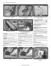
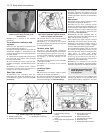
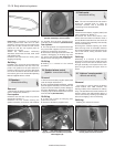
1 The main fuse and relay board is located
below the facia panel to the right of the
steering wheel. The fuses can be inspected
and if necessary renewed, by removing the
hinged access cover. The remaining
additional fuses and relays (depending on
model) may be accessed by removing the two
fuse board retaining screws, releasing the
retaining lugs on either side of the main fuse
plate and withdrawing the fuse/relay board
downwards into the driver’s footwell. Each
fuse location is numbered - refer to the fuse
chart in the Specifications at the start of this
Chapter to check which circuits are protected
by each fuse. Plastic tweezers are attached to
12•4 Body electrical systems
1595Ford Fiesta Remake