Rosemount Model 8800C Vortex Flowmeter with FOUNDATION
™
Fieldbus
6-4
ADVANCED
TROUBLESHOOTING
The Model 8800C electronics provides several advanced
troubleshooting features. These features enhance your ability to look
inside the electronics and can be helpful for troubleshooting inaccurate
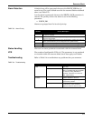
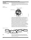
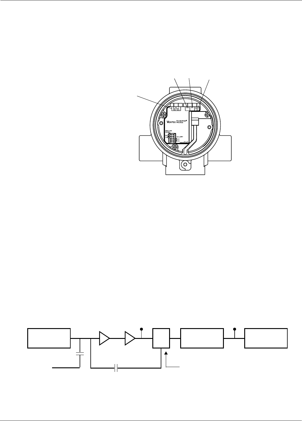
readings. As shown in Figure 6-1, there are several test points located
on the electronics.
FIGURE 6-1.
Electronics Test Points.
A digital representation of the filtered sensor shedding frequency is
available on the “SHEDDING FREQ OUT” pins shown in Figure 6-1.
The electronics are capable of internally generating a flow signal that
may be used to simulate a sensor signal to perform electronics
verification with any F
OUNDATION fieldbus-compliant host, such as the
DeltaV system with AMS from Fisher-Rosemount. The simulated signal
amplitude is based on the transmitter required minimum process
density. The signal being simulated can be one of several profiles – a
simulated signal of constant frequency or a simulated signal
representative of a ramping flow rate. The electronics verification
procedure is described in detail in Section 9: Electronics Verification.
To verify the electronics, you can input a frequency on the “TEST FREQ
IN” and “GND” pins to simulate flow via an external signal source such
as a frequency generator. To analyze and/or troubleshoot the
electronics, an oscilloscope (set for AC coupling) and a DeltaV with
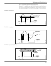
AMS interface are required. Figure 6-2 is a block diagram of the signal
as it flows from the sensor to the microprocessor in the electronics.
FIGURE 6-2. Signal Flow.
TP1
TP1 is the vortex shedding signal after it has gone through the charge
amplifier and low pass filter stages and into the input of the sigma delta
A-to-D converter ASIC in the electronics. The signal strength at this point
will be in the mV to Volt range.
8800-0000P03B
Shedding Freq Out
GND
TP1
Test Freq IN
8800-0572D
Sensor
Charge
Amplifier
Amplifier/Lo
w Pass Filter
A-to-D Converter Containing
Frequency Generator
External Test
Frequency
Input
TP1 Shedding Frequency Output
Digital Filter Microprocessor


