


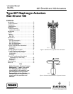

657 Size 80 and 100 Actuators
Instruction Manual
Form 1909
August 2006
9
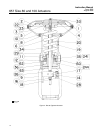
(used with group 1 springs only), and spring seat
(keys 115, 114, 35, and 11).
11. Remove seal bushing (key 111) and diaphragm
casing cover O-rings (keys 112 and 113) from upper
diaphragm casing (key 123). Replace with new parts
if necessary. Apply lithium grease lubricant to the
O-rings.
12. Remove actuator spring (key 6).
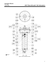
Size 100 Assembly
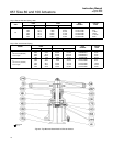
Note
Units using a group 2 spring require
one spring seat (key 11) on each end
of the spring (key 6); units using a
group 1 spring require only one spring
seat on the diaphragm end of the
spring as shown in figure 5.
1. Place the spring and spring seats (keys 6 and 11)
inside the spring case.
2. For actuators using a group 1 spring, pack the
thrust bearing (key 35) with lithium grease lubricant
(key 241). Place bearing on the spring seat.
3. Screw the hex jam nut and adjusting nut (keys
115 and 114) onto the actuator stem.
4. Install the lower diaphragm casing (key 5) on the
actuator tie rods (key 21). Secure with hex nuts.
Note
Before installing diaphragm plate (key
4), rotate adjusting nut (key 114) until
the top of the actuator stem is 264 mm
(10-3/8 inches) above the inside
surface of the lower casing (key 5).
When installing diaphragm (key 2), be
certain that the rubber side of the
diaphragm faces away from the spring.
CAUTION
To avoid product damage, smooth the
edge of the diaphragm to avoid
wrinkling, and be careful that the
diaphragm fold does not get pinched
when the upper casing (key 1) is
installed.
5. Install washer, diaphragm plate, diaphragm,
diaphragm retainer, and backup plate
(keys 117, 4, 2, 110 and 13).
6. Apply lithium grease lubricant (key 241) to the
thread on the diaphragm end of the actuator stem
(key 10).
7. Position the upper diaphragm casing (key 1) on
the diaphragm (key 2), and align the holes.
Note
If backup plate (key 13) interferes with
installation of upper casing, rotate
adjusting nut (key 114) to move the
plate.
Note
When you replace actuator
diaphragms in the field, take care to
ensure the diaphragm casing bolts are
tightened to the proper load to prevent
leakage, but not crush the material.
Perform the following tightening
sequence with a manual torque
wrench for size 80 and 100 actuators.
CAUTION
Over-tightening the diaphragm casing
cap screws and nuts can damage the
diaphragm. Do not exceed 68 NSm (50
lbfSft) torque.
Note
Do not use lubricant on these bolts
and nuts. Fasteners must be clean and
dry.
8. Insert the cap screws (key 22), and tighten the
hex nuts (key 23) in the following manner. The first
four hex nuts tightened should be diametrically
opposed and 90 degrees apart. Tighten these four
hex nuts to 34 NSm (25 lbfSft).
9. Tighten the remaining hex nuts in a clockwise,
criss-cross pattern to 34 NSm (25 lbfSft).
10. Repeat this procedure by tightening four hex
nuts, diametrically opposed and 90 degrees apart, to
a torque of 68 NSm (50 lbfSft).
11. Tighten the remaining hex nuts in a clockwise,
criss-cross pattern to 68 NSm (50 lbfSft).