


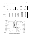
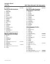
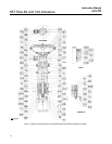

657 Size 80 and 100 Actuators
Instruction Manual
Form 1909
August 2006
12
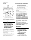
block (keys 133, 183, 175, and 179) into the body as
shown in figure 6 and install support screws
(key 182).
3. Install handwheel and hex nut (keys 51 and 54).
4. Install a new handwheel gasket (key 185).
5. Mount the handwheel assembly on the
diaphragm casing, and secure with cap screws
(key 141).
6. Reconnect pressure tubing or piping to actuator
casing.
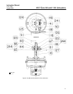
Size 100 Top-Mounted Handwheel
(Adjustable Up Travel Stop)
A top-mounted handwheel assembly is normally
used as an adjustable-up travel stop to limit full
retraction of the actuator stem. Clockwise rotation of
the handwheel (key 51) moves the actuator stem
(key 10) downward, compressing the spring (key 6).
Spring action returns the stem as the handwheel is
turned counterclockwise. Instructions are given
below for complete disassembly and assembly.
Perform the disassembly only as far as necessary to
accomplish the required maintenance; then, begin
the assembly at the appropriate step.
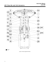
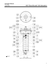
Key numbers refer to figure 5 for actuator parts and
figure 8 for handwheel parts.
Disassembly
1. Bypass the control valve. Reduce the loading
pressure to atmospheric (refer to the Maintenance
section), and remove the tubing or piping from the
diaphragm casing.
WARNING
To avoid personal injury from the
precompressed spring force thrusting
the upper diaphragm casing (key 1)
away from the actuator, relieve spring
compression (step 2, below), and
carefully remove casing cap screws
(key 124) (step 3, below).
2. Rotate handwheel counterclockwise, relieving all
spring compression.
3. Unscrew cap screws (key 124), and remove gear
case cover (key 123).
4. Loosen the set screws (key 41) in the front and
back worm retainers (keys 48 and 49) and
handwheel (key 51).
5. Remove retaining ring (key 118), and remove
handwheel.
6. Remove front and back worm retainers (keys 48
and 49).
7. Remove worm shaft (key 45).
8. Pull the power screw assembly (key 122). The
bearing and gear retainer, thrust bearing, and worm
gear (keys 66, 67 and 44) will come out with the
power screw.
Assembly
1. Pack the ball bearings (key 50) with lithium
grease lubricant (key 241), and insert one ball
bearing into the back worm retainer (key 49).
2. Thread the back worm retainer and ball bearing
into the gear case. Align the slot in the worm retainer
with the set screw hole in the gear case, insert set
screw (key 41), and tighten.
3. Coat the worm shaft (key 45) threads with lithium
grease lubricant, and slide the shaft into the gear
case so that the end of the shaft fits snugly in the
back worm retainer.
4. Insert the bearing into the front worm retainer
(key 48), and thread the retainer and ball bearing
into the gear case. Align the slot in the retainer with
the hole in the gear case, insert the set screw
(key 41), and tighten.
5. Slide the handwheel onto the worm shaft
(key 45), and install retaining ring (key 118).
6. Pack the two thrust bearings (key 67) with lithium
grease lubricant. Install one thrust bearing, then the
worm gear (key 44), followed by the second thrust
bearing and the bearing and gear retainer (key 66).
7. Coat the power screw threads (key 122) with
lithium grease lubricant. Slide the power screw into
the thrust bearing (key 67), turn the handwheel, and
feed the sleeve through the worm gear.
8. Adjust set screws (key 40) to eliminate free play
in the bearings.
Note
Over-tightening the set screws will
make handwheel operation difficult.
9. Install gear case cover (key 123), and tighten cap
screws (key 124).