


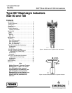

657 Size 80 and 100 Actuators
Instruction Manual
Form 1909
August 2006
7
9. Unscrew cap screws and nuts (keys 62 and 63),
and remove spring case (key 29). Cap screws
(key 62) on units with side-mounted handwheel do
not use hex nuts (key 63).
10. For actuators without side-mounted handwheel,
remove adjusting flange (key 36) and attached thrust
bearing and adjusting screw (keys 35 and 12).
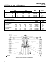
11. For actuators with side-mounted handwheel
(see figure 7), unscrew cap screws (key 64), and
remove adjusting flange (key 36) and attached thrust
bearing and adjusting screw (keys 35 and 12). Do
not lose the key (key 47).
Size 80 Assembly
1. Coat the threads of the adjusting flange (key 36)
with anti-seize lubricant (key 244). Replace the
adjusting flange, adjusting screw, and thrust bearing
(keys 36, 12, and 35). Pack bearing with lithium
grease lubricant (key 241).
For actuators with side-mounted handwheel, install
the key (key 47) on the adjusting flange (key 36).
Coat the adjusting flange threads with anti-seize
lubricant. Install the adjusting flange so that the key
engages the slot in the lower sleeve. Secure
adjusting flange with cap screws (key 64). Adjust set
screws (key 40, figure 7) to eliminate free play in
handwheel bearings.
Note
Over-tightening the set screws will
make handwheel operation difficult.
2. Mount the spring case (key 29) to the yoke (key
9) using cap screws and hex nuts (keys 62 and 63).
3. Position the lower spring seat (key 11), and slide
the actuator spring (key 6) squarely onto the spring
seat.
4. If the diaphragm plate and actuator stem (keys 4
and 10) were separated, fasten them together using
the cap screw (key 3) and tighten to a torque of 544
NSm (400 lbfSft).
For actuators without a hydraulic snubber, slide
upper sleeve (key 34) onto the actuator stem, and
then slide upper sleeve, actuator stem and
diaphragm plate into the spring case (key 29) so that
the spring (key 6) fits squarely between the
diaphragm plate and the spring seat (key 11).
For actuators with a snubber, thread the actuator
stem and upper spring seat (keys 10 and 90) into the
piston/piston rod assembly (key 27). Install the
snubber assembly and attached actuator stem into
the upper sleeve, spring case adaptor, and spring
case (keys 34, 72, and 29). Secure with cap screws
(key 85).
5. Place the diaphragm (key 2) with pattern side
facing away from the diaphragm plate (key 4). Align
the holes in the diaphragm and the lower diaphragm
casing (key 5).
6. Position the upper diaphragm casing (key 1) on
the diaphragm (key 2), and align the holes.
Note
When you replace actuator
diaphragms in the field, take care to
ensure the diaphragm casing bolts are
tightened to the proper load to prevent
leakage, but not crush the material.
Perform the following tightening
sequence with a manual torque
wrench for size 80 and 100 actuators.
CAUTION
Over-tightening the diaphragm casing
cap screws and nuts can damage the
diaphragm. Do not exceed the
following maximum torque values for
the appropriate diaphragm material:
EPDM/Meta-Aramid: 95 NSm (70 lbfSft)
Nitrile, Silicone, FKM
(fluorocarbon)/Meta-Aramid: 68 NSm
(50 lbfSft)
Note
Do not use lubricant on these bolts
and nuts. Fasteners must be clean and
dry.