


657 Size 80 and 100 Actuators
Instruction Manual
Form 1909
August 2006
11
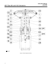
flange so that the key engages the slot in the lower
sleeve. Secure adjusting flange with cap screws
(key 64).
9. Adjust set screws (key 40) to eliminate free play
in the bearings.
Note
Over-tightening the set screws will
make handwheel operation difficult.
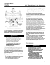
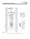
10. Install the adjusting screw and thrust bearings
(keys 12 and 35). Pack bearings with lithium grease
lubricant (key 241), and install as shown in figure 7.
11. Slide the spring case (key 29) into position, and
secure with cap screws (key 62).
12. Complete steps 3 through 8 of the size 80
actuator assembly section.
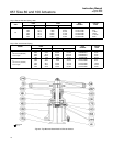
Size 80 Hydraulic Snubber
The size 80 Type 657 is available with a hydraulic
snubber, as shown in figure 7, to dampen vertical
instability of actuator stem movement. The snubber
is adjusted by rotating the adjusting screws (key 83,
figure 7) counterclockwise out of the reservoir (key
79, figure 7) to increase damping action and
clockwise to decrease damping action. The adjusting
screw on the right (the lower of the two adjusting
screws in section B-B of figure 7) regulates
downward damping action, and the screw on the left
regulates upward damping action.
Size 80 Top-Mounted Handwheel
(Adjustable Up Travel Stop)
CAUTION
If repeated or daily manual operation is
expected, and the actuator is equipped
with a casing-mounted travel stop or
top-mounted handwheel, the
diaphragm could be subject to
excessive wear.
The actuator should be equipped with
a side-mounted handwheel, which is
designed for more frequent use as a
manual operator.
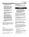
A top-mounted handwheel assembly is normally
used as an adjustable-up travel stop to limit full
retraction of the actuator stem. Turning the
handwheel clockwise turns the handwheel stem
(key 133, figure 6) into the diaphragm casing and
forces the pressure block assembly (key 179,
figure 6) against the diaphragm and diaphragm
plate. Instructions are given below for complete
disassembly and assembly. Perform the
disassembly only as far as necessary to accomplish
the required maintenance; then, begin the assembly
at the appropriate step.
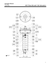
Key numbers refer to figure 4 for actuator parts and
figure 6 for handwheel parts.
Disassembly
1. Bypass the control valve. Reduce the loading
pressure to atmospheric, and remove the tubing or
piping from the diaphragm casing (key 1).
WARNING
To avoid personal injury from the
precompressed spring force thrusting
the upper diaphragm casing (key 1)
away from the actuator, relieve spring
compression (step 2, below), and
carefully remove casing cap screws
(key 141) (step 3, below).
2. Remove cover band (key 60). Insert a rod of
approximately 12.7 mm (1/2-inch) diameter into a
hole in the adjusting screw (key 12), and rotate the
adjusting screw from right to left until spring
compression is relieved. Rotate handwheel to be
sure it is not compressing actuator spring.
3. Unscrew cap screws (key 141), and remove
handwheel assembly.
4. Remove hex nut (key 54), and lift off the
handwheel.
5. Unscrew support screws (key 182), and remove
pressure block, stem, stem collar, and thrust bearing
(keys 179, 133, 183, and 175).
6. Unscrew body nut (key 186), and remove gland
(key 180). If necessary, remove and replace packing
rings (key 181).
Assembly
1. Install new packing rings and gland (keys 181
and 180), and thread the body nut (key 186) onto the
body.
2. Lubricate the thrust bearing and stem (keys 175
and 133), with lithium grease lubricant (key 241).
Slide stem, stem collar, thrust bearing, and pressure