


657 Size 80 and 100 Actuators
Instruction Manual
Form 1909
August 2006
5
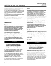
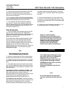
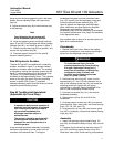
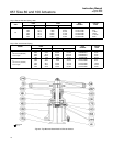
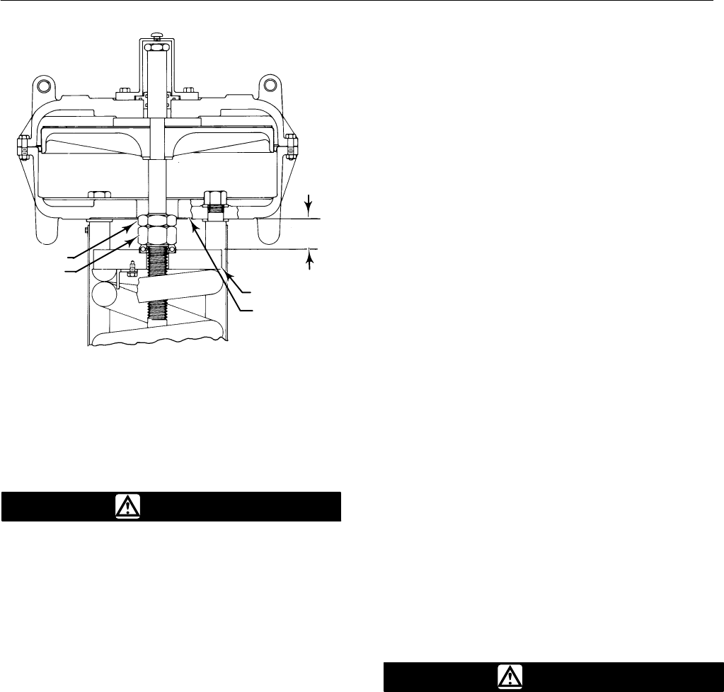
Figure 3. Dimension B for Spring Adjustment
LOWER
DIAPHRAGM
CASING
SPRING SEAT
JAM NUT
ADJUSTING
NUT
A0950-1 / IL
B
For high spring forces, it is necessary to use spacers
between the lower diaphragm casing and the spring
seat to isolate spring force from the adjusting nut.
WARNING
To avoid personal injury from the
compressed actuator spring snapping
back to its original length, make and
use the spacers by following the
instructions in the steps below.
To avoid personal injury, keep hands
and tools away from the spring and
spring seat as instructed in the
following procedure.
1. It is recommended that three spacers be made
of 3-inch schedule 80 pipe cut to the appropriate
length specified in step 2. If other than the
recommended material is to be used, be certain that
the spacers are capable of withstanding the spring
force involved. The spacers must be of equal length
with ends cut squarely.
2. Measure dimension B as shown in figure 3. Cut
length of spacers as follows:
a. If it is desired to decrease spring compression,
make the spacers approximately 4.8 mm
(3/16-inch) longer than dimension B.
b. If it is desired to increase spring compression,
make the spacers approximately 4.8 mm
(3/16-inch) shorter than either dimension B plus
the amount of adjustment required or dimension
B plus valve travel, whichever is less.
3. Whenever the total amount of adjustment
required is greater than valve travel, the adjustment
must be made in two or more steps, and the amount
of adjustment taken in each step must be less than
valve travel.
4. Pressure the actuator to attain full travel.
Cautiously insert the spacers at equal intervals
around the spring seat (key 11, figure 5). The
spacers must be seated squarely when in use or
they may slip out of position. Keeping hands and
tools away from the spring and spring seat, slowly
decrease loading pressure until the spring force
holds the spacers firmly between the spring seat and
lower diaphragm casing (key 5, figure 5).
5. Loosen the jam nut. The adjusting nut can now
be rotated clockwise (when viewed from the
diaphragm casings) to increase the loading pressure
required to start actuator stem travel or
counterclockwise to decrease the pressure required
to start travel.
6. Pressure the actuator to move the spring seat
away from the spacers, and carefully remove the
spacers.
7. If the total adjustment required was greater than
valve travel, repeat the procedure. It will be
necessary to make new spacers using the new
dimension B and the remaining adjustment required
or valve travel, whichever is less. Tighten the jam
nut when adjustment is complete.
Maintenance
WARNING
Avoid personal injury or property
damage from sudden release of
process pressure or bursting of parts.
Before performing any maintenance
operations:
D Always wear protective gloves,
clothing, and eyewear when
performing any maintenance
operations to avoid personal injury.
D Disconnect any operating lines
providing air pressure, electric power,
or a control signal to the actuator. Be