


657 Size 80 and 100 Actuators
Instruction Manual
Form 1909
August 2006
6
sure the actuator cannot suddenly
open or close the valve.
D Use bypass valves or completely
shut off the process to isolate the
valve from process pressure. Relieve
process pressure from both sides of
the valve. Drain the process media
from both sides of the valve.
D Vent the power actuator loading
pressure and relieve any actuator
spring precompression.
D Use lock-out procedures to be
sure that the above measures stay in
effect while you work on the
equipment.
D The valve packing box may
contain process fluids that are
pressurized, even when the valve has
been removed from the pipeline.
Process fluids may spray out under
pressure when removing the packing
hardware or packing rings, or when
loosening the packing box pipe plug.
D Check with your process or safety
engineer for any additional measures
that must be taken to protect against
process media.
The maintenance instructions are divided into four
sections: actuator (sizes 80 and 100); side-mounted
handwheel assembly (manual operator); hydraulic
snubber; and top-mounted handwheel assembly
(adjustable-up travel stop).
Actuator
This procedure describes how the actuator can be
completely disassembled and assembled. When
inspection or repairs are required, disassemble only
those parts necessary to accomplish the job; then,
start the assembly at the appropriate step.
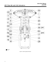
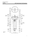
Key numbers refer to figure 4 for size 80 actuators
and figure 5 for size 100 actuators.
Size 80 Disassembly
1. Bypass the control valve. Reduce the loading
pressure to atmospheric, and remove the tubing or
piping from the top of the diaphragm casing (key 1).
WARNING
To avoid personal injury from the
precompressed spring force thrusting
the upper diaphragm casing (key 1)
away from the actuator, relieve spring
compression (step 2, below), and
carefully remove casing cap screws
(key 22) (step 4, below).
2. Remove cover band (key 60). Insert a rod of
approximately 12.7 mm (1/2-inch) diameter into a
hole in the adjusting screw (key 12), and rotate the
adjusting screw from right to left until spring
compression is relieved. If the actuator has a
handwheel, rotate it counterclockwise, relieving all
spring compression.
3. If necessary, the entire actuator may be removed
from the valve body by unscrewing two cap screws
from stem connector (key 26) and removing
actuator-to-bonnet bolting.
4. Unscrew diaphragm casing cap screws and nuts
(keys 22 and 23), and lift off upper diaphragm casing
(key 1).
5. Remove the molded diaphragm (key 2).
6. For actuators without snubber, remove
diaphragm plate and stem (keys 4 and 10) as an
assembly. This assembly can be broken down
further, if necessary, by removing the cap screw
(key 3).
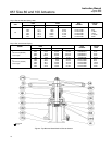
7. For actuators with snubber (see figure 7),
unscrew cap screw (key 3), and remove diaphragm
plate (key 4). Remove stem connector (key 26).
Unscrew cap screws (key 85), and remove cylinder
assembly (key 74) and attached stem and upper
seat (keys 10 and 90) from actuator.
To disassemble snubber:
a. Unscrew stem from piston/piston rod
assembly (key 27).
b. Remove retaining rings, cylinder heads, and
piston/piston rod assembly (keys 76, 75, and 27).
Replace packing and O-rings (keys 103, 104, 77
and 105) as required.
8. Remove actuator spring, upper sleeve, and
spring seat (keys 6, 34 and 11).