


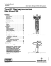

657 Size 80 and 100 Actuators
Instruction Manual
Form 1909
August 2006
3
Installation
WARNING
To avoid personal injury or parts
damage, do not exceed the Maximum
Diaphragm Casing Pressure listed in
table 1. The Maximum Diaphragm
Casing Pressure must not produce a
force on the actuator stem greater than
the maximum allowable actuator
output thrust or the maximum
allowable stem load.
Always wear protective gloves,
clothing, and eyewear when
performing any installation operations
to avoid personal injury.
Check with your process or safety
engineer for any additional measures
that must be taken to protect against
process media.
If installing into an existing
application, also refer to the WARNING
at the beginning of the Maintenance
section in this instruction manual.
When an actuator and valve body are shipped
together, the actuator is normally mounted on the
valve. Follow the valve body instructions when
installing the control valve in the pipeline. If the
actuator is shipped separately or if it is necessary to
mount the actuator on the valve, perform the
Actuator Mounting procedures as described below.
For information on mounting valve positioners, refer
to the appropriate valve positioner instruction
manual.
Actuator Mounting
1. To permit adjustment of the actuator spring, the
size 100 actuator must be installed in a vertical
position above the valve body. Mount the actuator
on the valve bonnet. Insert the cap screws, and
tighten the hex nuts, securing the actuator to the
bonnet.
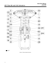
2. Screw valve stem locknuts (key 16, figure 4) all
the way onto valve stem thread.
3. Connect an air supply to the diaphragm casing.
4. For push-down-to-close valves, be sure the valve
plug is on its seat. Apply pressure to ensure that the
actuator stem is fully extended. Reduce actuator
loading pressure to retract the stem approximately
3.2 mm (1/8-inch).
5. For push-down-to-open valves, move valve plug
to closed position. On large body sizes, this may
require the use of a pry bar inserted through the
body line opening. If the body is installed in a
pipeline, the bottom flange (if one is used) can be
removed and the valve plug pushed to the seat from
the bottom opening. Pressure the actuator to move
the stem out 3.2 mm (1/8-inch).
WARNING
To avoid personal injury due to the
sudden uncontrolled movement of
parts, do not loosen the stem
connector cap screws when the stem
connector has spring or loading
pressure force applied to it.
CAUTION
Incomplete engagement of both valve
stem and actuator stem in the stem
connector can result in stripped
threads or improper operation. Be sure
that the length of each stem clamped
in the stem connector is equal to or
greater than the diameter of that stem.
6. Clamp the actuator and valve plug stems
between the two stem connector halves (key 26,
figure 4). Insert and tighten the stem connector cap
screws.
7. Thread the stem locknuts against the stem
connector.
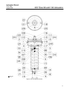
8. Align the travel indicator scale (key 18, figures 4
and 5) to show valve position.
Loading Connection
1. Connect the loading pressure piping to the
connection in the top of the diaphragm casing.
2. Remove the 1/4-inch bushing (key 33, figure 4
and key 120, figure 5) to increase connection size, if
necessary. The connection can be made with either
piping or tubing.
3. Keep the length of tubing or piping as short as
possible to avoid transmission lag in the control
signal. If an accessory (such as a volume booster or
valve positioner) is used, be sure that the accessory