


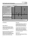
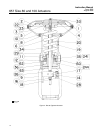
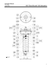

657 Size 80 and 100 Actuators
Instruction Manual
Form 1909
August 2006
10
12. After the last hex nut is tightened to 68 NSm (50
lbfSft), all of the hex nuts should be tightened again
to 68 NSm (50 lbfSft) in a circular pattern around the
bolt circle.
13. Once completed, no more tightening is
recommended.
14. Install the actuator stem extension (key 116),
diaphragm casing cover O-rings (keys 112 and 113),
and seal bushing (key 111). Install the gear case
cover (key 123) or the handwheel assembly (see
figure 8).
15. Mount the actuator on the valve, and secure
with the actuator-to-bonnet bolting. Refer to the
Installation section to connect actuator stem to valve
plug stem.
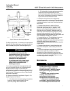
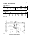
Size 80 Side-Mounted Handwheel
The side-mounted handwheel assembly (figure 7) is
normally used as a manual operator. The handwheel
can be mounted in either of two positions so that,
regardless of valve plug action, counterclockwise
rotation always opens the valve. The assembly is a
continuously connected type with an indicator to
show neutral position. By rotating handwheel away
from neutral, the handwheel can be used to limit
travel in either direction but not both directions at the
same time.
A grease fitting is provided on the gear box for
periodic gear lubrication with a general-purpose
grease.
Instructions are given below for complete
disassembly and assembly. Perform the
disassembly only as far as necessary to accomplish
the required maintenance; then, begin the assembly
at the appropriate step.
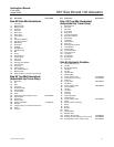
Key numbers refer to figure 7.
Disassembly
1. Complete steps 1 through 9 of the disassembly
portion of the size 80 actuator section.
2. Unscrew cap screws (key 64), and remove
adjusting flange (key 36). Do not lose the key
(key 47).
3. Unscrew the two screws (key 28), and remove
travel stop indicator (key 58) from lower sleeve
(key 46).
4. Turn handwheel (key 51) to raise lower sleeve.
Continue turning handwheel until lower sleeve is free
of worm gear (key 44). Lift out lower sleeve, bearing
and gear retainer, thrust bearings, and worm gear
(keys 46, 66, 67, and 44).
5. The worm shaft (key 45) and associated parts
can be removed in order to replace or lubricate
them. First, remove the handwheel cap (key 54) and
the handwheel (key 51). Do not lose the small ball or
spring (keys 55 and 56).
6. Loosen the two set screws (key 41), and unscrew
the two worm retainers (keys 48 and 49). The ball
bearings (key 50) will come out with the retainers.
Remove the worm shaft (key 45).
Assembly
1. Pack the ball bearings (key 50) with lithium
grease lubricant, and insert one ball bearing in the
back worm retainer (key 49) as shown in figure 7
(section C-C).
2. Thread the back worm retainer and ball bearing
(keys 49 and 50) into the gear case. Align the slot in
the worm retainer with the set screw hole in the gear
case, insert the set screw (key 41), and tighten it.
3. Coat the worm shaft (key 45) threads with
anti-seize lubricant (key 244), and slide the shaft into
the gear case so that the end of the shaft fits snugly
in the back worm retainer.
4. Insert the bearing in the front worm retainer
(key 48), and thread the retainer and ball bearing
into the gear case. Align the slot in the retainer with
the set screw hole in the gear case, insert the set
screw (key 41), and tighten it.
5. Put the spring and ball (keys 56 and 55) in the
handwheel (key 51). Slide the handwheel onto the
worm shaft (key 45). Thread the handwheel cap
(key 54) onto the worm shaft.
6. Pack the two thrust bearings (key 67) with lithium
grease lubricant. Install one thrust bearing; then,
install the worm gear (key 44) followed by the
second thrust bearing and the bearing and gear
retainer (key 66).
7. The lower sleeve (key 46) has two screw holes in
one end. Coat the sleeve threads with lithium grease
lubricant, slide the end of the lower sleeve with the
holes into the thrust bearing (key 67), turn the
handwheel, and feed the sleeve through the worm
gear. Continue turning the handwheel until the lower
sleeve protrudes from the gear case. Fasten the
travel stop indicator (key 58) to the sleeve with the
two machine screws (key 28).
8. Install the key (key 47) on the adjusting flange
(key 36). Coat the adjusting flange threads with
anti-seize lubricant (key 244). Install the adjusting