


removed and the weight of the car is again on
its roadwheels.
4 Fill the cooling system.
5 Fill the engine with oil.
6 Replenish lost transmission oil.
7 Reconnect the battery.
8 Adjust the clutch pedal as described in
Chapter 5.
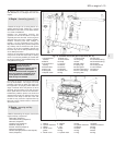
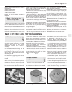
24 Engine - initial start-up after
overhaul or major repair
4
1 Make sure that the battery is fully charged
and that all lubricants, coolant and fuel are
replenished.
2 If the fuel system has been dismantled it will
require several revolutions of the engine on
the starter motor to pump the petrol up to the
carburettor.
3 Turn the carburettor throttle speed screw
through one complete turn to increase the idle
speed in order to offset the initial stiffness of
new engine internal components.
4 As soon as the engine fires and runs, keep
it going at a fast idle speed and bring it up to
normal working temperature.
5 As the engine warms up there will be odd
smells and some smoke from parts getting
hot and burning off oil deposits. The signs to
look for are leaks of water or oil which will be
obvious.
6 Check also the exhaust pipe and manifold
connections as these do not always “find”
their exact gas tight position until the warmth
and vibration have acted on them and it is
almost certain that they will need tightening
further. This should be done, of course, with
the engine stopped.
7 When normal running temperature has
been reached, adjust the engine idle speed as
described in Chapter 3.
8 Stop the engine and wait a few minutes to
see if any lubricant or coolant is dripping out
when the engine is stationary.
9 Road test the car to check that the timing is
correct and that the engine is giving the
necessary smoothness and power. Do not
race the engine - if new bearings and/or
pistons have been fitted it should be treated
as a new engine and run in at a reduced
speed for the first 500 km (300 miles).
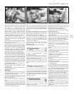
10 After the first 1500 km (900 miles) the
cylinder head bolts must be re-torqued in the
following way (engine cold).
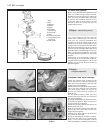
11 Remove the air cleaner and rocker cover.
Unscrew the first bolt (Fig. 1.7) through a
quarter turn and then tighten it to final stage 2
torque (see Specifications).
12 Repeat on the remaining bolts, one at a
time.
13 Check and adjust the valve clearances
(Section 5).
14 Refit the rocker cover and air cleaner.
903 cc engine 1•23
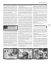
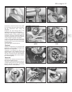
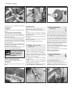
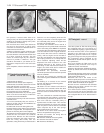
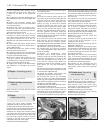
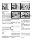
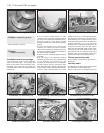
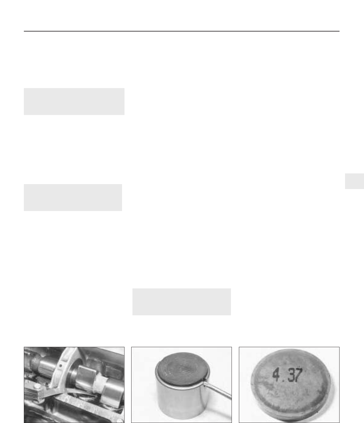
26.4 Shim engraved mark26.2 Removing a shim from a cam follower25.4 Checking a valve clearance
1
Part 3: 1116 cc and 1301 cc engines
25 Valve clearances - checking
2
This should only be required if the valves
have been renewed or ground in, or at high
mileages when noise or poor engine
performance indicates that a check is
necessary.
It is important that each valve clearance is
set correct otherwise the timing will be
wrong and engine performance poor. If there
is no clearance at all, the valve and its seat
will soon burn. Always set the clearances
with the engine cold.
1 Remove the camshaft cover. Jack-up a
front wheel and engage top gear so that by
turning the wheel, the crankshaft can be
rotated.
2 Each valve clearance must be checked
when the high point of the cam is pointing
directly upward away from the cam follower.
3 Check the clearances in the firing order
1-3-4-2, No. 1 cylinder being at the timing
belt end of the engine. This will minimise the
amount of crankshaft rotation required.
4 Insert the appropriate feeler blade
between the heel of the cam and the cam
follower shim of the first valve. If necessary
alter the thickness of the feeler blade until it
is a stiff, sliding fit. Record the thickness,
which will, of course, represent the valve
clearance for this particular valve (photo).
5 Turn the crankshaft, check the second
valve clearance and record it.
6 Repeat the operations on all the remaining
valves, recording their respective clearances.
7 Remember that the clearance for inlet and
exhaust valves differs - see Specifications.
Counting from the timing cover end of the
engine, the valve sequence is:
Inlet 2-3-6-7
Exhaust 1-4-5-8
26 Valve clearances -
adjustment
3
1 Check the valve clearances (Section 25).
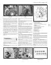
2 Clearances which are incorrect will mean
the particular shim will have to be changed.
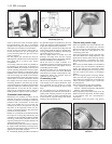
To remove the shim, turn the crankshaft until
the high point of the cam is pointing directly
upward. The cam follower will now have to
be depressed so that the shim can be
extracted. Special tools (A60642 and
A87001) are available from your Fiat dealer to
do the job, otherwise you will have to make
up a forked lever to locate on the rim of the
cam follower. This must allow room for the
shim to be prised out by means of the
cut-outs provided in the cam follower rim
(photo).
3 Once the shim is extracted, establish its
thickness and change it for a thicker or
thinner one to bring the previously recorded
clearance within specification. For example,
if the measured valve clearance was 1.27
mm (0.05 in) too great, a shim thicker by this
amount will be required. Conversely, if the
clearance was 1.27 mm (0.05 in) too small, a
shim thinner by this amount will be required.
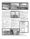
4 Shims have their thickness (mm) engraved
on them; although the engraved side should
be fitted so as not to be visible, wear still
occurs and often obliterates the number. In
this case, measuring their thickness with a
metric micrometer is the only method to
establish their thickness (photo).