


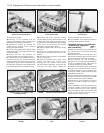
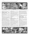
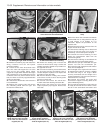
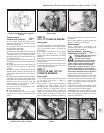
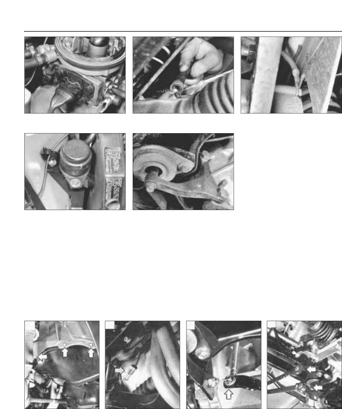
20 Release the retaining clip and detach the
wiring connector from the fuel injector
connection (photo).
21 Loosen off the front wheel bolts each
side, then raise and support the car at the
front end on axle stands. When raised,
support at a height which will allow the engine
and transmission to be withdrawn from the
underside when fully disconnected. Ensure
that the vehicle is securely supported before
working underneath it.
22 Unscrew the wheel bolts and remove the
front roadwheels.
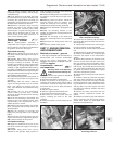
23 Release the retaining clips and remove
the underwing shield from the right- and
left-hand front wheel arch.
24 Relieve the staking, then unscrew and
remove the front hub nut using a socket and
suitable extension. Repeat the procedure on
the opposite front hub.
25 Unscrew the retaining nut and disconnect
the tie-rod to steering arm balljoint using a
suitable balljoint separator tool. Repeat the
procedure on the other side.
26 Note the direction of fitting, then unscrew
and remove the hub-to-strut retaining bolts
and nuts on each side.
27 Unscrew and remove the anti-roll bar-
to-track control arm retaining nuts each side.
28 Unscrew and remove the front brake
caliper hydraulic pipe support bracket bolt
each side.
29 Pull the wheel hub outwards and detach
the driveshaft from it, noting that there may be
a small amount of oil spillage as it is
withdrawn. Repeat the procedure on the
opposite side.
30 Disconnect the wiring connector from the
engine oil level sensor lead.
31 Unscrew the retaining nuts to detach and
remove the exhaust pipe front section or
alternatively, remove the system complete.
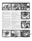
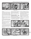
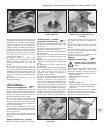
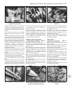
32 Unscrew the knurled retaining nut and
detach the speedometer cable from the
transmission (photo).
33 Unscrew the retaining nut and detach the
earth strap from the transmission (photo).
34 Extract the split pin and detach the gear
selector rod from the transmission pin.
Disconnect the gear engagement and selector
levers from the balljoints.
35 The weight of the engine will now need to
be supported from above. Connect a suitable
lift hoist and sling to the engine. When
securely connected, take the weight of the
engine/transmission unit so that the tension is
relieved from the mountings.
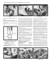
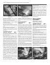
36 Unscrew and remove the engine and
transmission support mounting bolts at the
points indicated (photos).
37 The engine/transmission unit should now
be ready for removal from the vehicle. Check
that all of the associated connections and
13•50 Supplement: Revisions and information on later models
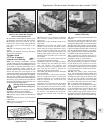
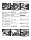
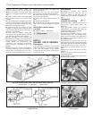
Fig. 13.22 The underwing
shield retaining clips (arrowed)
on the 1372 cc ie and Turbo ie
engines (Sec 7C)
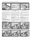
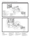
Fig. 13.25 Gear engagement
and selector lever balljoints
(arrowed) on the 1372 cc ie and
Turbo ie engines (Sec 7C)
Fig. 13.23 Engine oil level
sensor wiring connector
(arrowed) on the 1372 cc ie and
Turbo ie engines (Sec 7C)
Fig. 13.24 Disconnect the gear
selector rod at the connection
indicated on the 1372 cc ie and
Turbo ie engines (Sec 7C)
7C.33 Disconnect the transmission earth
strap
7C.32 Disconnecting the speedometer
drive cable from the transmission
7C.20 Fuel injector wiring connection
7C.36B Transmission rear mounting7C.36A Engine right-hand mounting